Multiple-acting linear actuator

a linear actuator and actuator technology, applied in the direction of toothed gearings, machines/engines, jet propulsion plants, etc., can solve the problems of complex electronic or mechanical synchronization of the actuating means, cumbersome solutions,

Inactive Publication Date: 2010-08-05
AIRCELLE
View PDF21 Cites 132 Cited by
  • Summary
  • Abstract
  • Description
  • Claims
  • Application Information

AI Technical Summary

Benefits of technology

[0015]Thus, by providing a single rotationally driven body able to transmit said rotational movement to one or more concentric bodies through mutually interacting screw threads, the various moving bodies are automatically synchronized through the screw threads. The relative sizing of the screw threads allows the speeds of relative translational movement of the bodies with respect to one another to be adapted from the starting point of an identical rotational drive speed.
[0018]According to a first alternative form of embodiment, the external screw thread of the central body has a pitch that is longer (coarser) than the pitch of the internal screw thread. The speed of translational movement of the external body will therefore be higher than the speed of translational movement of the internal body.
[0019]According to a second alternative form of embodiment, the external screw thread of the central body has a pitch that is shorter (finer) than the pitch of the internal screw thread. The speed of translational movement of the external body will therefore be lower than the speed of translational movement of the internal body.
[0029]Thus, by driving the actuator according to the invention through the agency of the external body, it is possible to achieve this synchronization in an easy way.

Problems solved by technology

However, a solution such as this is cumbersome and entails complex electronic or mechanical synchronizing of the actuating means.

Method used


Image

  • Multiple-acting linear actuator
  • Multiple-acting linear actuator
  • Multiple-acting linear actuator

Examples


first embodiment

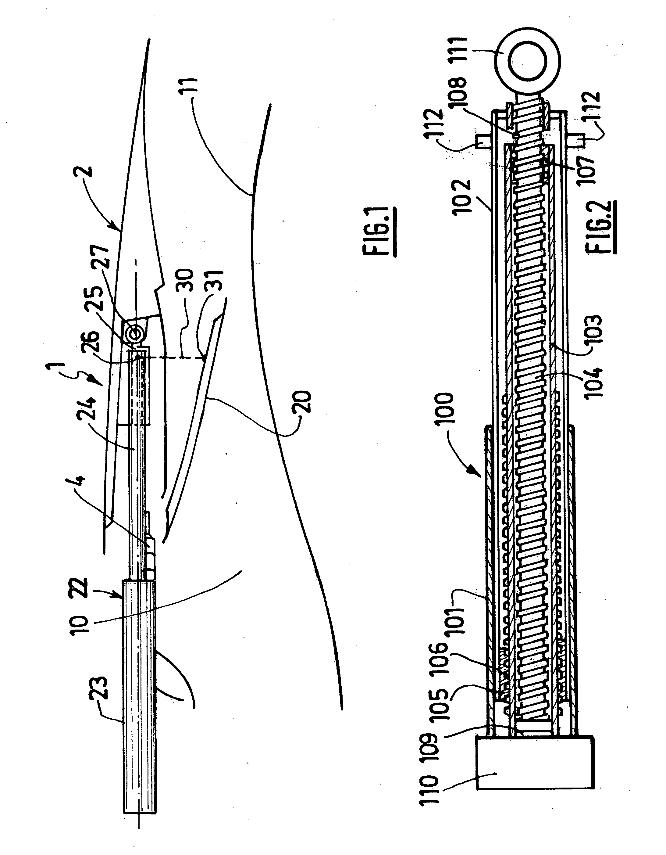
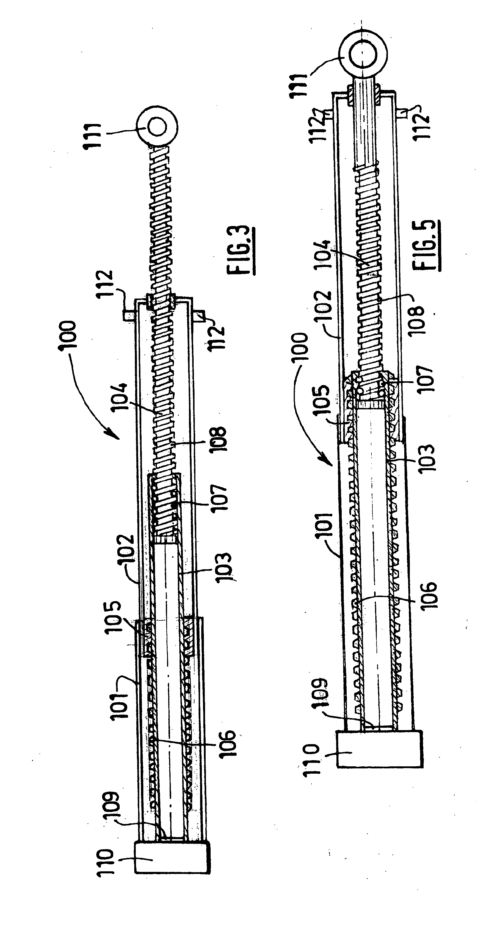
[0049]FIGS. 1 to 5 show an actuator according to the invention intended for actuating a moving cowl of a reverser equipped with a shut-off shutter.

[0050]FIG. 1 is a schematic part view in longitudinal section on a plane passing through cascades of deflection vanes, of a cascade-type thrust reverser equipped with a shut-off shutter as described in application FR 06.09265 in the thrust-reversal situation.

[0051]In the known way, the thrust reverser 1 depicted in FIG. 1 is associated with a bypass turbojet engine (not depicted) and comprises an external nacelle which, together with a concentric internal structure 11, defines an annular flow duct 10 for a secondary flow path.

[0052]A longitudinally sliding cowl 2 includes two semi-cylindrical parts mounted on the nacelle in such a way as to be able to slide along slideways (not depicted).

[0053]An opening fitted with cascades of fixed deflection vanes 4 is formed in the external nacelle of the thrust reverser 1. This opening, when the gase...

second embodiment

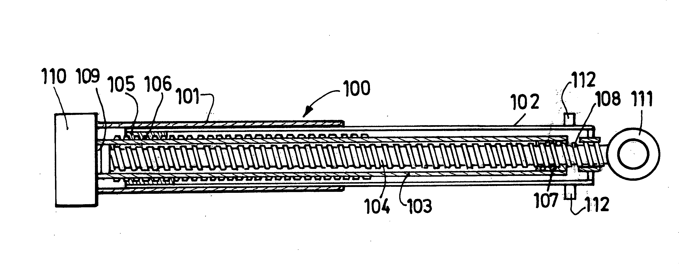
[0078]Each moving part of this thrust-reversal system can be translationally driven using a single actuator 203 according to the invention.

[0079]Like the actuator 100, the actuator 203 comprises an external body 204, a central body 205 and an internal body 206, all of these being concentric.

[0080]The external body 204 is mechanically engaged with the central body 205 and for this purpose has an internal screw thread 207 engaged with a corresponding external screw thread 208 of the central body 205.

[0081]Further, the central body 205 has an internal screw thread 209 engaged with a corresponding external screw thread 210 of the internal body 206.

[0082]The external body 204 is mounted fixed in terms of rotation movement but able to move in terms of translational movement and is connected to rotational drive means 211 housed in a casing 212 that forms a base of the actuator.

[0083]The internal body 206 for its part is capable of translational movement but prevented from turning.

[0084]Thu...


PUM


Abstract

The present invention relates to a multiple-acting linear actuator (100) intended to drive at least two elements capable of moving relative to a fixed element comprising a plurality of rod-forming concentric tubular bodies (103, 102, 104) engaged successively one inside the next via external and / or internal screw threads (105, 106, 107, 108), characterized in that one of the bodies is connected to rotational-drive means (109), the other bodies then together forming an internal and / or external transmission train, and in that said bodies are associated with selective lock-up means whereas the outermost bodies of the internal and / or external transmission trains are permanently prevented from rotating.

Description

TECHNICAL FIELD[0001]The present invention relates to a telescopic linear actuator for moving a first element and a second element relative to one another and with respect to a fixed element, these three elements in particular belonging to a thrust reverser of a turbojet engine nacelle as described for example in the as yet unpublished French patent application filed under the No. 06.09265 and in the likewise as yet unpublished French application filed under the No. 06.05512, both filed in the name of the Applicant Company and incoproated herein by reference.BACKGROUND[0002]An airplane is propelled by a number of turbojet engines each housed in a nacelle that also houses a collection of auxiliary actuating devices associated with its operation and for forming various functions when the turbojet engine is operating or not operating. These auxiliary actuating devices comprise, for example, a mechanical system for actuating thrust reversers.[0003]A nacelle generally has a tubular struc...

Claims


Application Information

Patent Timeline
Patent Type & Authority Applications(United States)
IPC IPC(8): F16H27/02
CPCF02K1/763F16H25/20F16H25/2056Y10T74/18672F16H2025/2084F16H2025/2093F16H2025/2075
Inventor VAUCHEL, GUYBAUDU, PIERRE
Owner AIRCELLE
Why Eureka
Try Eureka