Screwdriver

Inactive Publication Date: 2010-08-05
MILWAUKEE ELECTRIC TOOL CORP
View PDF99 Cites 38 Cited by
  • Summary
  • Abstract
  • Description
  • Claims
  • Application Information

AI Technical Summary

Problems solved by technology

All three types of drivers have disadvantages when used with a combination head fastener.
Phillips-head drivers are self-centering within the fastener head, but have a te

Method used


Image

  • Screwdriver
  • Screwdriver
  • Screwdriver

Examples


Embodiment Construction

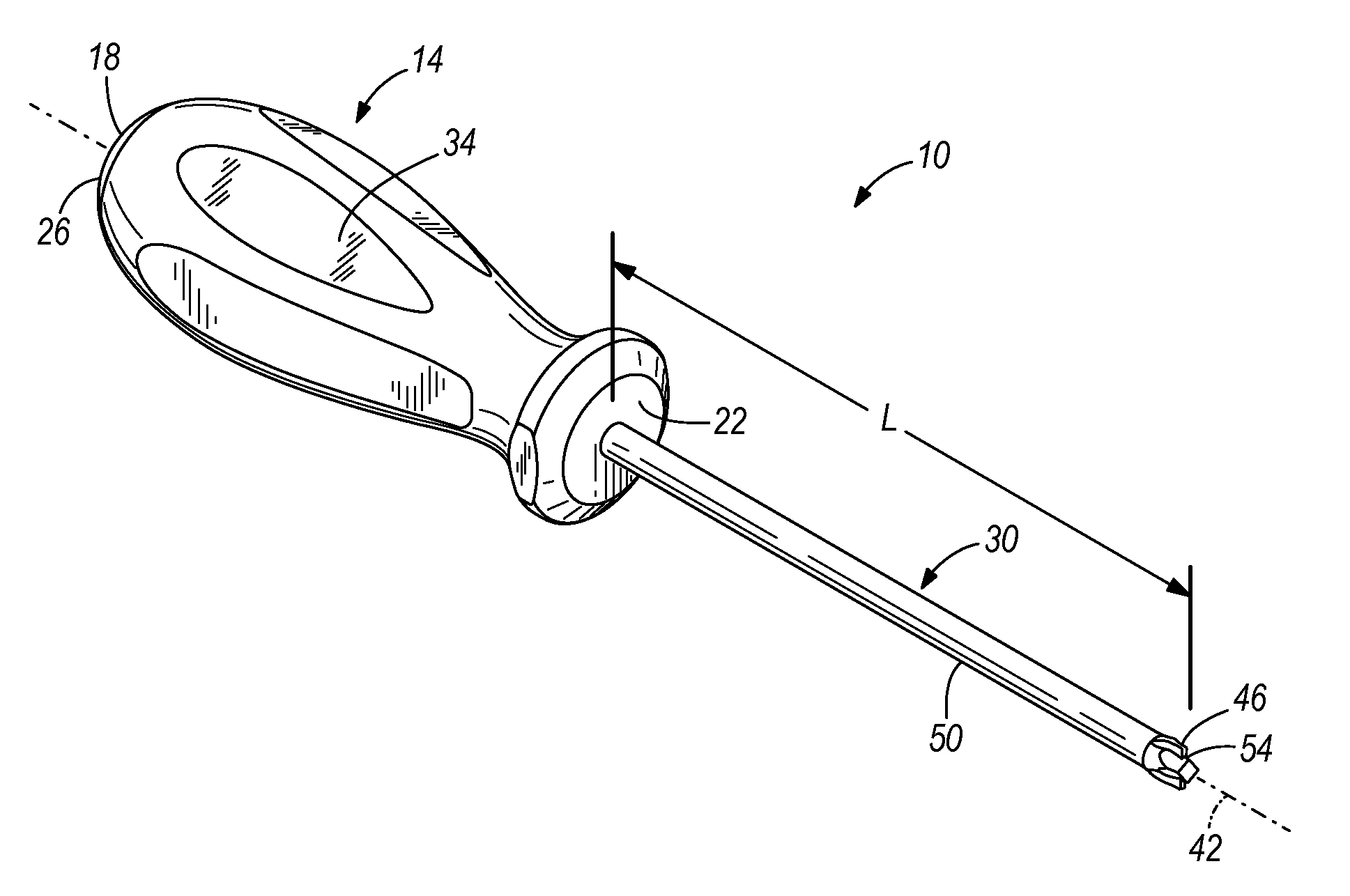
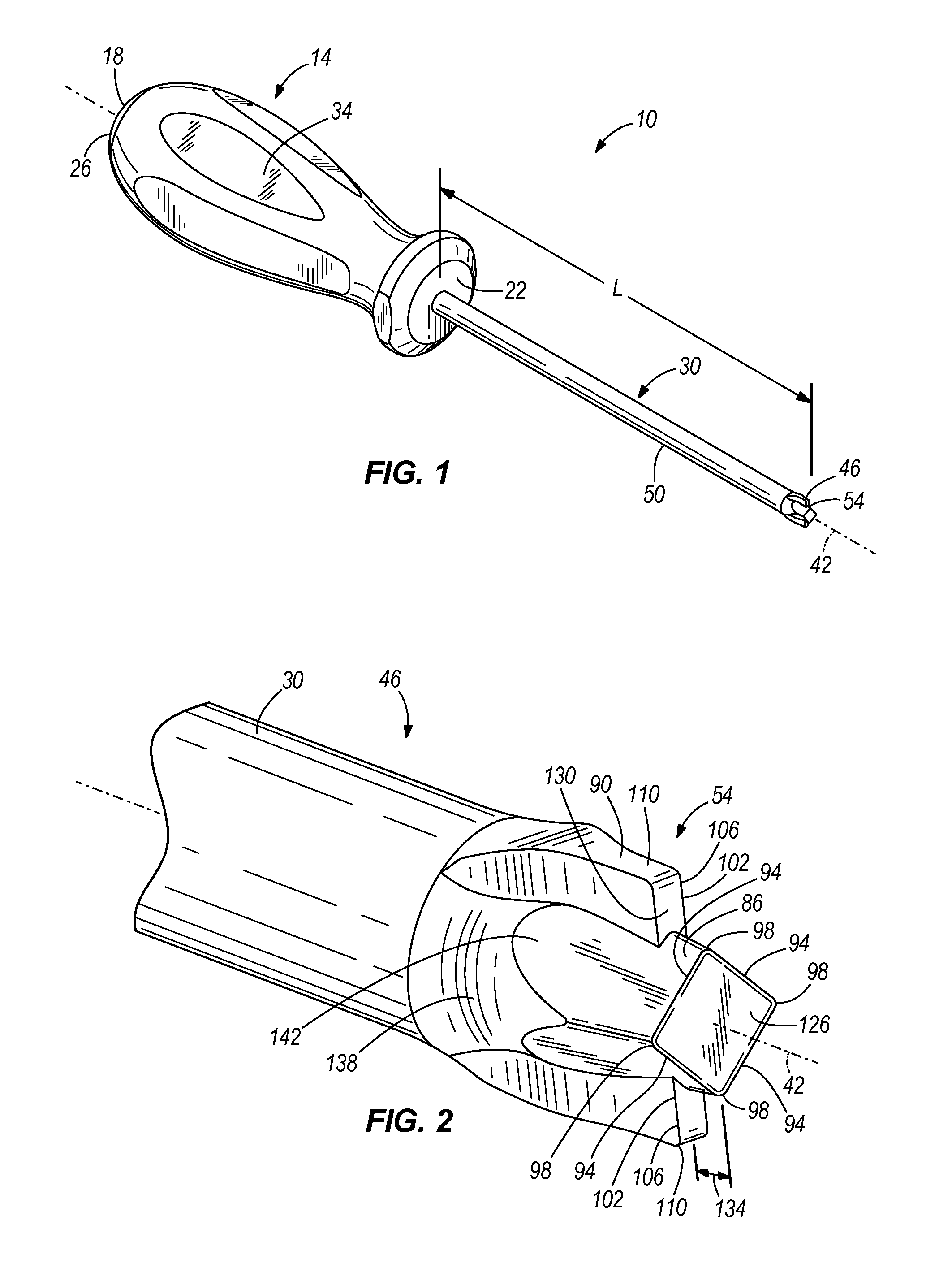
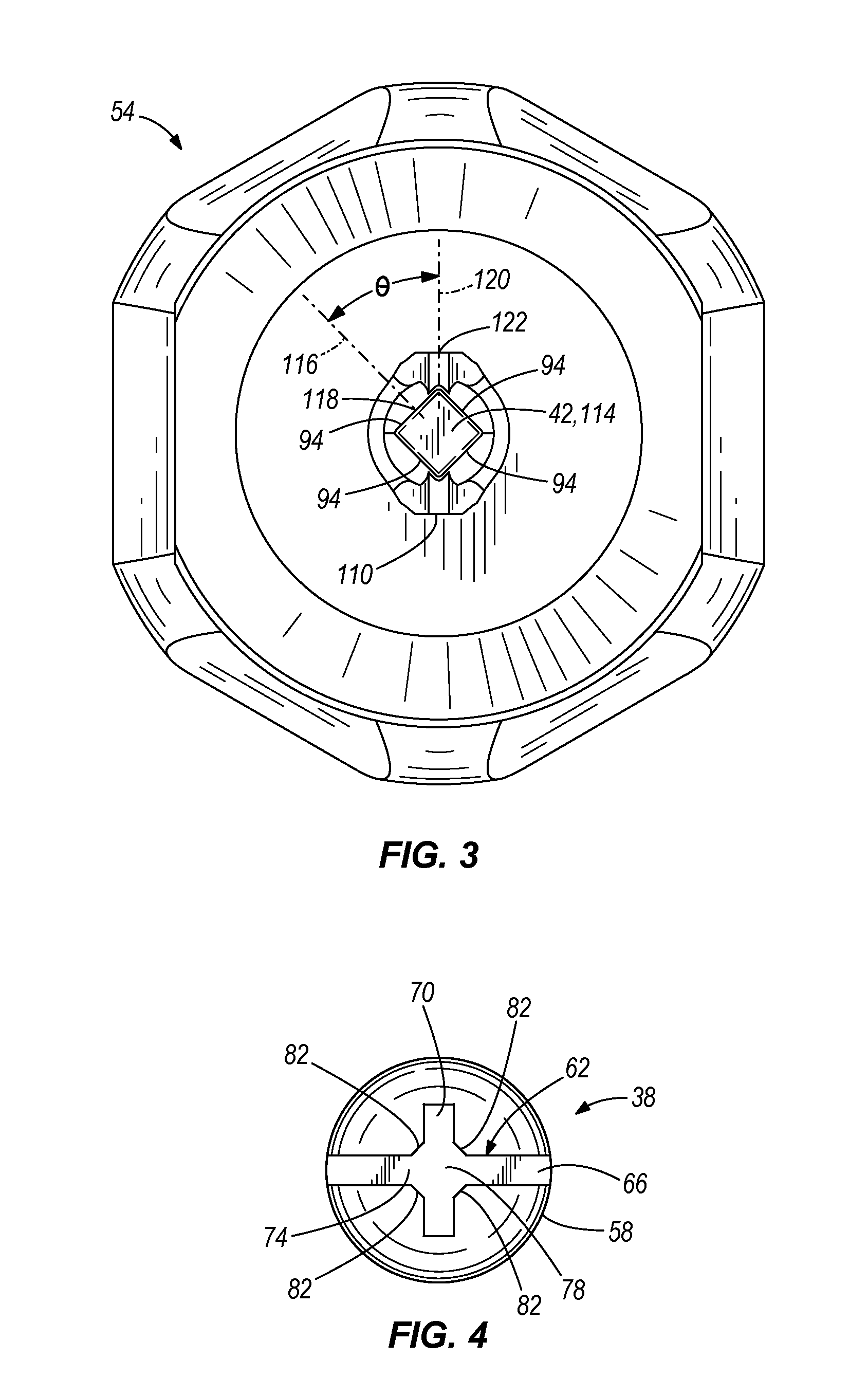
[0020]FIGS. 1-3 illustrate a screwdriver 10 according to one embodiment of the invention. The screwdriver 10 includes a handle 14 having a first end 18 and a second end 22. A rounded pommel 26 is formed at the first end 18 of the handle 14, and screwdriver shaft 30 projects outwardly from the second end 22 of the handle 14. The handle 14 also includes gripping surfaces 34 for a user such that the user may grip the handle 14 for the tightening and loosening of a fastener, such as a screw head 38 (FIG. 4). The handle 14 is coupled to the shaft 30, and the user transmits torque from the handle 14 to the screw head 38 via the shaft 30. In the illustrated embodiment, the handle 14 is fixedly coupled to the shaft 30. In further embodiments, the handle 14 may be molded over a shaft extension, unitarily formed with the shaft, or otherwise fixedly or detachably coupled to the shaft.

[0021]The shaft 30 extends from the handle 14 along a central axis 42 and includes a driver end 46. A shaft len...


PUM


Abstract

A driver tool configured to engage and drive the head of a threaded fastener includes a shank defining a longitudinal axis. The shank has a mating end and a driver end. A driver head is coupled to the shank adjacent the driver end. The driver head includes a first driving portion having a substantially square cross section normal to the axis and a geometric center along the axis. The first driving portion includes four walls and a corner at an intersection of adjacent walls such that the first driving portion includes a first corner, a second corner, a third corner opposite the first corner, and a fourth corner opposite the second corner. The driver head further includes a second driving portion including a first flange extending radially outward from the first driving portion and a second flange extending radially outward from the first driving portion. The second flange is opposite the first flange, and each of the flanges includes an end wall having a midpoint. A plane passing through the first corner and the third corner of the first driving portion passes through the midpoints of the end walls of the second driving portion.

Description

CROSS-REFERENCE TO RELATED PATENT APPLICATION[0001]This application claims priority to U.S. Provisional Patent Application No. 61 / 150,153, filed Feb. 5, 2009, the entire contents of which is incorporated by reference herein.BACKGROUND OF THE INVENTION[0002]The present invention relates to a hand tool, and in particular a drive device for combination head fasteners.[0003]Combination or “combo” head fasteners were developed to be driven by either a conventional flat-head type driver or a Phillips-head type driver. Some combination fastener head designs can also receive a Robertson type square driver. All three types of drivers have disadvantages when used with a combination head fastener. Flat-head drivers require a user to manually hold the driver bit substantially centered in the fastener head slot and aligned with the axis of the fastener shank, and care must be taken to maintain alignment between the fastener and driver. Phillips-head drivers are self-centering within the fastener...

Claims


Application Information

Patent Timeline
IPC IPC(8): B25B23/00B25B15/00
CPCB25B15/005B25B15/008B25B15/007
Inventor BURCH, WADESTEELE, MICHAEL S.
Owner MILWAUKEE ELECTRIC TOOL CORP
Why Eureka
Try Eureka