Differential Pressure Seed Meter With An Endless Belt Seed Transport Member

a technology of seed meter and seed transport member, which is applied in the field of seed meter, can solve the problems of physical limitations of equipment size, adversely affecting seed pick-up and singulation, and the need to increase the diameter of the disk, so as to achieve greater freedom

Active Publication Date: 2010-08-05
DEERE & CO
View PDF11 Cites 83 Cited by
  • Summary
  • Abstract
  • Description
  • Claims
  • Application Information

AI Technical Summary

Benefits of technology

[0005]The present invention utilizes an endless belt as a seed metering and seed transport member together with a pressure differential to hold the seed onto the belt. The flexibility of the belt enables the spatial orientation of the belt to vary from location to location where different seed meter functions are performed. The bel...

Problems solved by technology

However, there are physical limitations regarding the size of the equipment.
To increase the planting speed with such a disk, the disk must rotate faster, which may adversely impact seed pick-up and s...

Method used


Image

  • Differential Pressure Seed Meter With An Endless Belt Seed Transport Member
  • Differential Pressure Seed Meter With An Endless Belt Seed Transport Member
  • Differential Pressure Seed Meter With An Endless Belt Seed Transport Member

Examples


Embodiment Construction

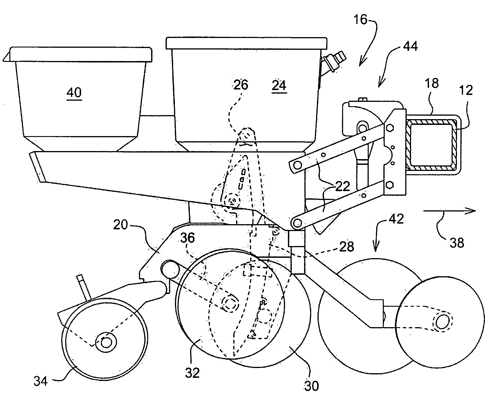
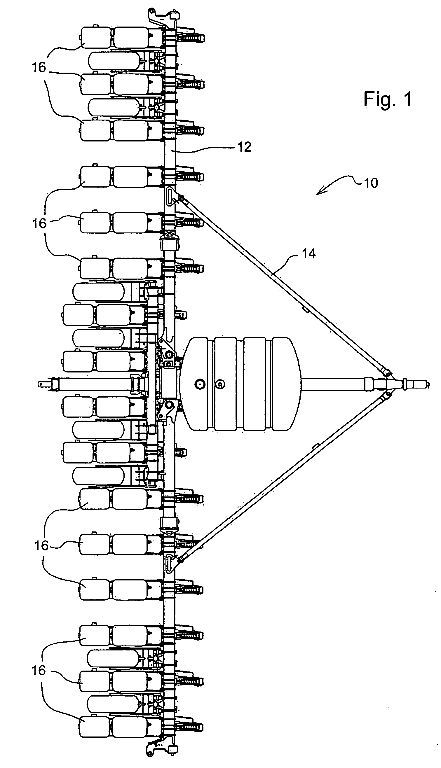
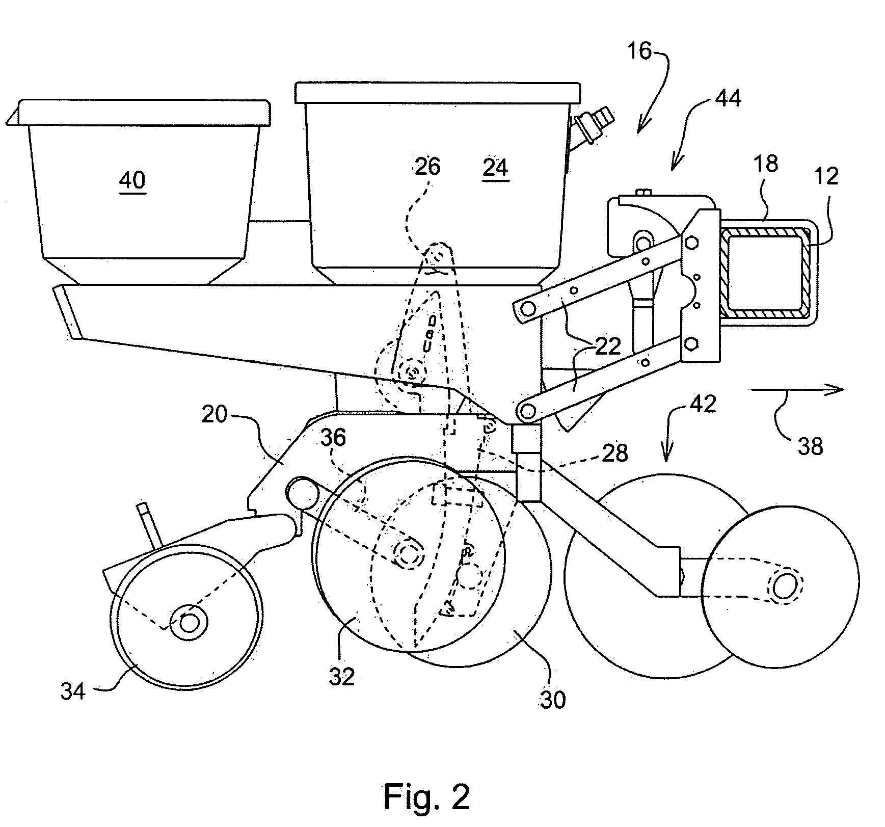
[0027]With reference to FIG. 1 an example planter 10 is shown containing the differential pressure seed meter of the present invention. Planter 10 includes a tool bar 12 as part of a planter frame 14. Mounted to the tool bar are multiple planting row units 16. A row unit 16 is shown in greater detail in FIG. 2. The row unit 16 is mounted to the tool bar 12 in a conventional manner. The row unit 16 is provided with a central frame member 20 having a pair of upwardly extending arms 21 (FIG. 3) at the forward end thereof. The arms 21 connect to a parallelogram linkage 22 mounting the row unit 16 to the tool bar 12 for up and down relative movement between the unit 16 and toolbar 12 in a known manner. Seed is stored in seed hopper 24 and provided to seed meter 26. Seed meter 26 functions to select seeds individually and provide the seed to a placing mechanism, a seed tube 28 in FIG. 3 for delivery of the seed to a planting furrow formed in the soil by furrow openers 30. Gauge wheels 32 ...


PUM


Abstract

A seed meter is provided having an endless belt as a seed transport member together with a pressure differential to hold the seed onto the belt. The use of an endless belt as the seed transport member enables the spatial orientation of the seed transport member to vary from location to location along the path of the belt where different seed meter functions are performed. The belt allows greater freedom in determining the location of the seed pick-up region and the seed release or removal region beyond the constraints of a fixed diameter seed disk. The belt further allows for a narrow envelope seed meter which can cross-feed seed into a substantially vertically oriented delivery device.

Description

FIELD OF THE INVENTION[0001]The present invention relates to a seed meter for a planter or seeder and in particular to a seed meter having an endless belt seed transport member.BACKGROUND OF THE INVENTION[0002]Farmers, like others, seek to increase their productivity. As farm sizes increase more work must be done in the same period of time. For example, the planting season on a farm extends over a fixed period of days. To increase the area farmed, the farmer must plant cropson the increased area in the same planting season or reduce crop yield. As a result, there is a need for planting equipment capable of covering more area per day. One approach to increase productivity is to increase the width of the planting equipment. However, there are physical limitations regarding the size of the equipment. Another approach is to increase the operating speed of the planting equipment.[0003]One common form of planter utilizes a vacuum disk seed meter for each row unit of the planter. One examp...

Claims


Application Information

Patent Timeline
IPC IPC(8): A01C7/08A01C19/00
CPCA01C7/127A01C7/042
Inventor GARNER, ELIJAHFRIESTAD, MICHAEL E.MARIMAN, NATHAN A.
Owner DEERE & CO
Why Eureka
Try Eureka