Indicating instrument for vehicle

a technology for indicating instruments and vehicles, applied in the direction of compasses, speed/acceleration/shock measurement devices, program control, etc., can solve the problem of difficult to accurately control the rotation of the pointer

Active Publication Date: 2010-08-05
DENSO CORP
View PDF27 Cites 13 Cited by
  • Summary
  • Abstract
  • Description
  • Claims
  • Application Information

AI Technical Summary

Problems solved by technology

Accordingly, it is difficult to accurately control the rotation of the pointer after the loss of synchronization by the drive signal that corresponds to the electrical angle in the indicating instrument for a vehicle of Japanese Patent No. 3770095.

Method used


Image

  • Indicating instrument for vehicle
  • Indicating instrument for vehicle
  • Indicating instrument for vehicle

Examples


first embodiment

[0030]A first embodiment of the invention will be described below with reference to the accompanying drawings. An indicating instrument 1 for a vehicle is disposed in front of a driver seat inside the vehicle as a vehicle speed meter.

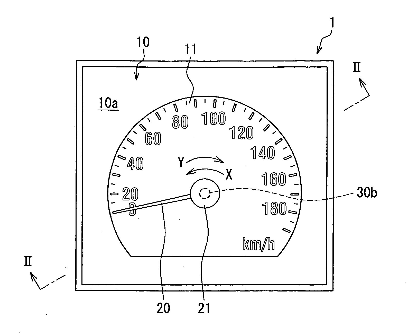
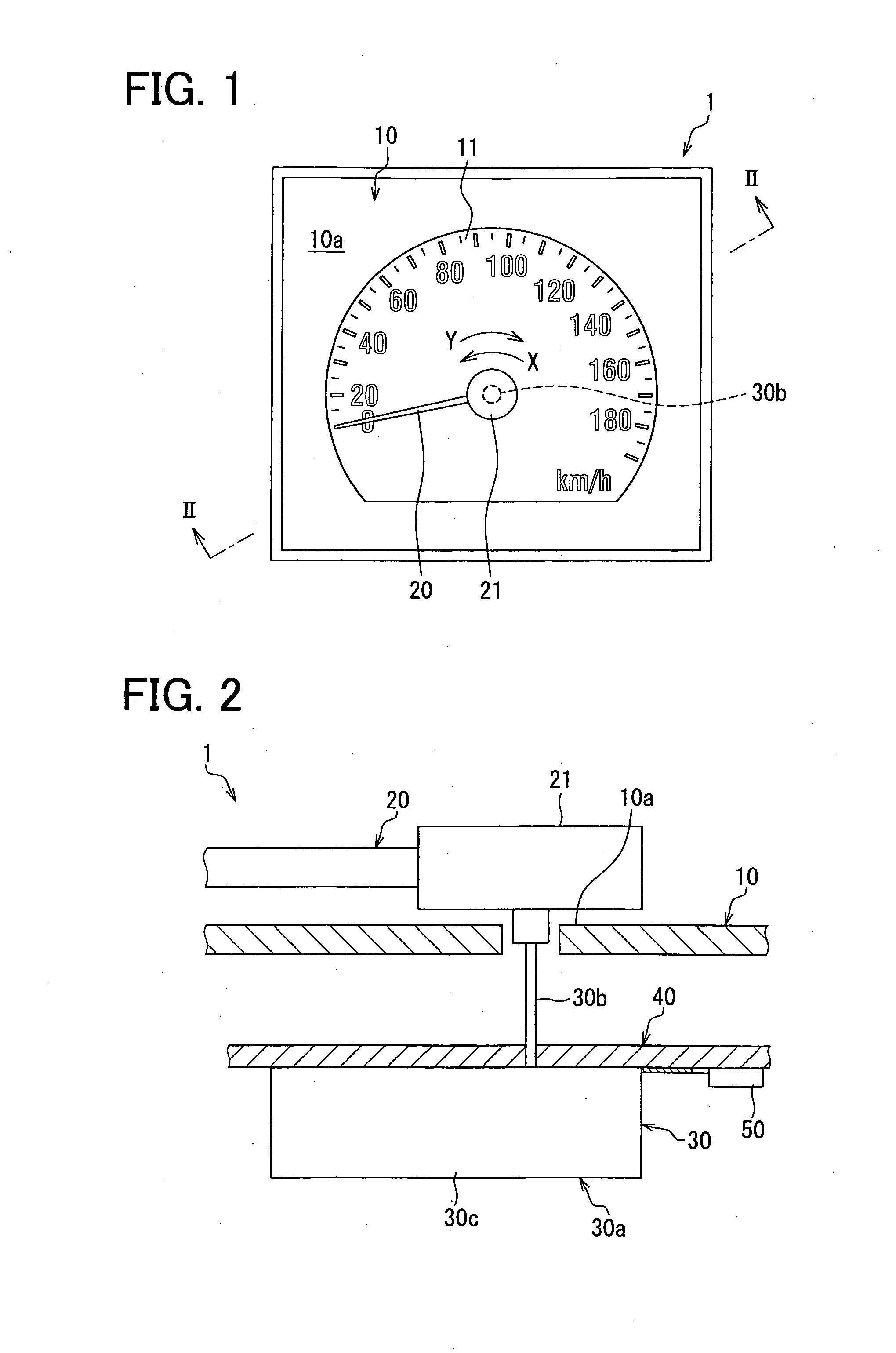
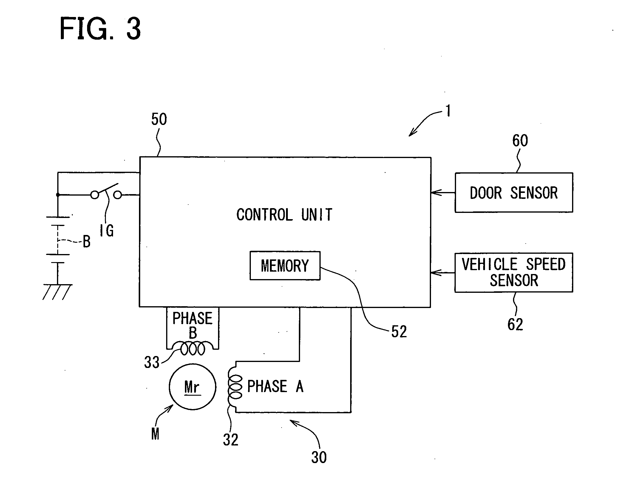
[0031]A structure of the indicating instrument 1 will be described in detail below. As illustrated in FIGS. 1 to 3, the indicating instrument 1 includes an instrument board 10, a pointer 20, a rotating inner device 30, a board 40, and a control unit 50. The control unit 50 may serve as a “detecting device” or a “control device.”

[0032]The instrument board 10 illustrated in FIGS. 1 and 2 is disposed with its display surface 10a directed toward the driver seat, and includes a vehicle speed display 11 that displays a vehicle speed value as a vehicle state value. The vehicle speed display 11 displays vehicle speed values in a shape of a circular arc from a zero value (0 km / h), which serves as their reference value, to an upper limit (180 km / h).

[0033]The poin...

second embodiment

[0070]A second embodiment of the invention will be described below with reference to the accompanying drawings. An indicating instrument 1 for a vehicle according to the second embodiment is disposed in front of a driver seat inside the vehicle as a vehicle speed meter. A structure of the indicating instrument 1 of the second embodiment is similar to that of the first embodiment. Therefore, detailed explanation of the structure of the indicating instrument 1 is omitted in the following description (see FIGS. 1 to 7).

[0071]A control flow for performing the initial processing by the control unit 50 in accordance with the second embodiment will be described in detail below with reference to FIG. 14. This control flow is started upon the start of the control unit 50.

[0072]At S201 of the control flow, synchronous control sub-processing is performed. More specifically, in the synchronous control sub-processing, the zero point θ0 and the phase interval ΔP that are stored in the memory 52 a...


PUM


Abstract

An indicating instrument for a vehicle includes a step motor including a field winding, a pointer, a stopper device for stopping the pointer, which is rotating in a zero-reset direction, at a stopper position, a detecting device for detecting induced voltage of the field winding at each of detecting points, a control device for performing zero-reset control, whereby a drive signal is controlled to rotate the pointer in the zero-reset direction. In a state of abnormal detection in which the induced voltage larger than a predetermined set value is detected at a zero point; and the induced voltage equal to or smaller than the set value is detected at a next detecting point to the zero point, the control device assumes synchronization loss of the step motor and continues the zero-reset control until an assumptive electrical angle corresponding to a rotational position of the pointer reaches the zero point.

Description

CROSS REFERENCE TO RELATED APPLICATION[0001]This application is based on and incorporates herein by reference Japanese Patent Application No. 2009-25213 filed on Feb. 5, 2009, and Japanese Patent Application No. 2009-25214 filed on Feb. 5, 2009.BACKGROUND OF THE INVENTION[0002]1. Field of the Invention[0003]The present invention relates to an indicating instrument for a vehicle.[0004]2. Description of Related Art[0005]Conventionally, an indicating instrument for a vehicle that rotates a pointer in synchronization with a step motor is known. The pointer indicates a vehicle state value, which is displayed with a zero value as its reference, in accordance with a rotational position of the pointer. The indicating instrument for a vehicle is described in Japanese Patent No. 3770095 (corresponding to U.S. Pat. No. 6,624,608B2), for example. This indicating instrument rotates a pointer through the application of a drive signal of an alternating current, which alternates in accordance with ...

Claims


Application Information

Patent Timeline
Patent Type & Authority Applications(United States)
IPC IPC(8): G01D11/16H02P8/08
CPCB60K37/02G01R7/06B60K2350/302B60K2370/42G01D2213/10
Inventor NAKANE, HIDEYUKI
Owner DENSO CORP
Why Eureka
Try Eureka