Speedcooking oven

Inactive Publication Date: 2010-08-05
GENERAL ELECTRIC CO
View PDF25 Cites 29 Cited by
  • Summary
  • Abstract
  • Description
  • Claims
  • Application Information

AI Technical Summary

Benefits of technology

[0007]According to one aspect of the present disclosure, an oven comprises a cooking cavity, a RF generation module, an upper heater module, a lower heater module and a convection heater module. The RF generation module is configured to deliver microwave energy into the cooking cavity. The upper heater module includes at least one of a halogen lamp and a ceramic heater. The lower heater module includes at least one of a halogen lamp and a ceramic heater. The upper and lower heater modules are configured to deliver primarily radiant energy into the cooking cavity. The convection heater module includes a sheath heater and a convection fan positioned to direct air over solely the sheath heater into the cooking cavity. The convection heater module is configured to deliver thermal energy into the cooking cavity. A control is operatively connected to the RF generation module, upper heater module, lower heater module and convection heater module for selective control thereof. The control operates the oven in a plurality of modes, including at least one and preferably all of the following modes, a microwave mode, a conve

Problems solved by technology

Radiant ovens, however, cook many foods slower than microwave ovens.
Such ovens, however, do not cook as fast as

Method used


Image

  • Speedcooking oven
  • Speedcooking oven
  • Speedcooking oven

Examples


Embodiment Construction

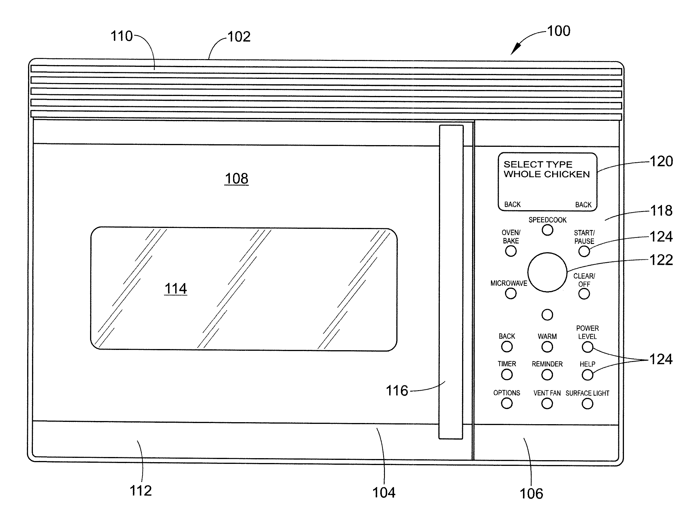
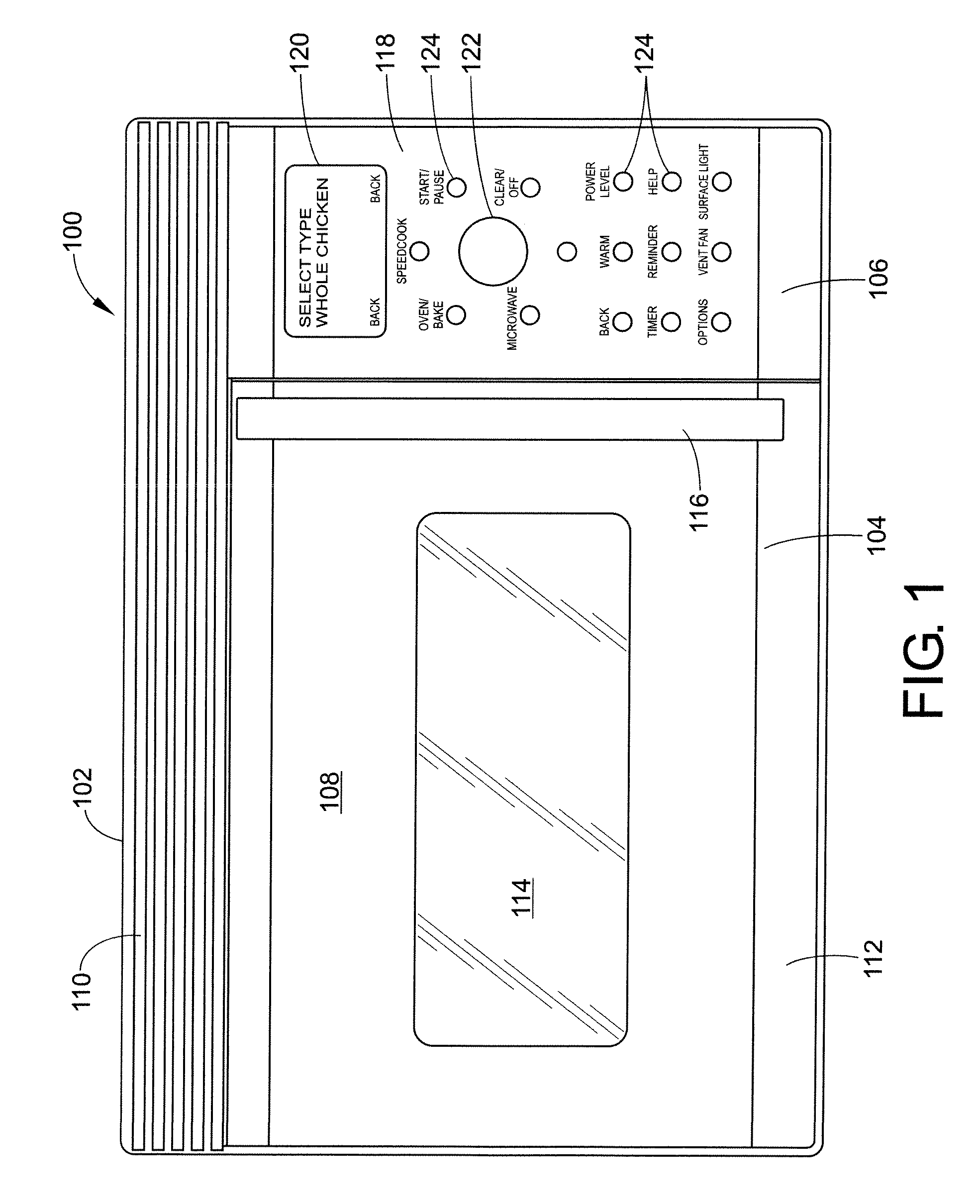
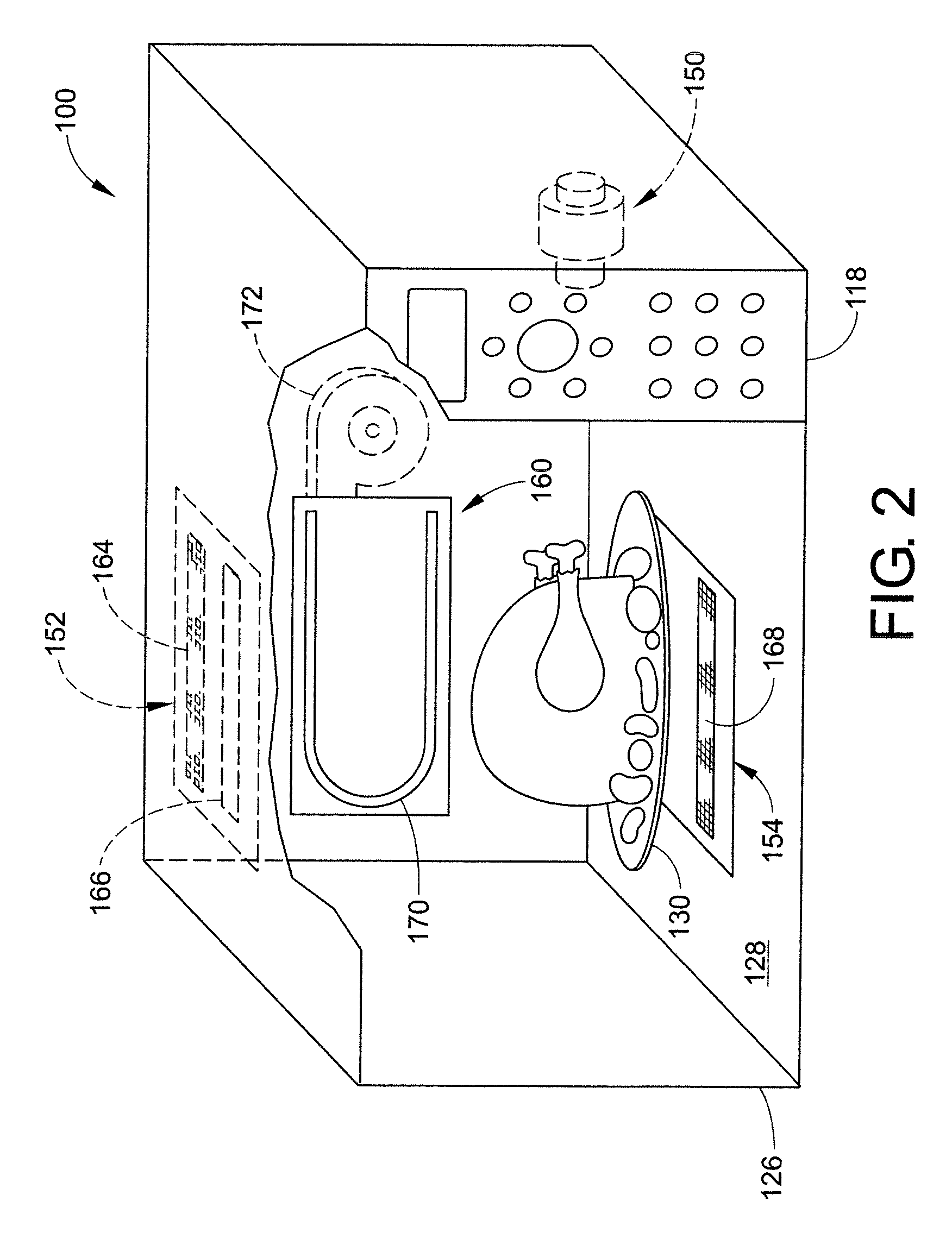
[0024]It should, of course, be understood that the description and drawings herein are merely illustrative and that various modifications and changes can be made in the structures disclosed without departing from the present disclosure. It will also be appreciated that the various identified components of the oven disclosed herein are merely terms of art that may vary from one manufacturer to another and should not be deemed to limit the present disclosure. Although one specific embodiment of an oven is described below, it should be understood that the present disclosure can be utilized in combination with many other such ovens and is not limited to practice with the oven described herein. For example, the oven described below is an over the range type oven. The present disclosure, however, is not limited to practice with just over the range type ovens and can be used with many other types of ovens such as countertop or built-in wall ovens.

[0025]Referring now to drawings, wherein li...


PUM


Abstract

An oven comprises a cooking cavity, a RF generation module, an upper heater module, a lower heater module and a convection heater module. The RF generation module is configured to deliver microwave energy into the cooking cavity. The upper heater module includes at least one of a halogen lamp and a ceramic heater. The lower heater module includes at least one of a halogen lamp and a ceramic heater. The convection heater module includes a sheath heater and a convection fan positioned to direct air over solely the sheath heater into the cooking cavity. The upper heater module and lower heater module are configured to deliver radiant energy into the cooking cavity. The convection heater module is configured to deliver thermal energy into the cooking cavity. A control is operatively connected to the RF generation module, upper heater module, lower heater module and convection heater module for selective control thereof. The control operates the oven in a plurality of modes, including a microwave mode, a convection/bake mode, and a speedcooking mode. In the speedcooking mode, the control is configured to selectively control the energization of the RF generation module, upper heating module and lower heating module concurrently with the selective energization of the convection heater module.

Description

BACKGROUND[0001]The present disclosure relates generally to ovens and, more particularly, to an oven operable in one of a speedcooking, microwave, and convection / bake mode.[0002]Ovens typically are either, for example, microwave, radiant, or thermal / convection cooking type ovens. For example, a microwave oven includes a magnetron for generating RF energy used to cook food in an oven cooking cavity. Although microwave ovens cook food more quickly than radiant or thermal / convection ovens, microwave ovens do not brown the food. Microwave ovens therefore typically are not used to cook as wide a variety of foods as radiant or thermal / convection ovens.[0003]Radiant cooking ovens include an energy source such as lamps which generate light energy used to cook the food. Radiant ovens brown the food and generally can be used to cook a wider variety of foods than microwave ovens. Radiant ovens, however, cook many foods slower than microwave ovens.[0004]In thermal / convection ovens, the food is ...

Claims


Application Information

Patent Timeline
IPC IPC(8): H05B6/64
CPCH05B6/6485
Inventor ZIMMER, THOMAS C.EDBERG, KAREN M.OLOKO, AKINTOYE OLADIPOCURL, DEREKYOUNG, MICHAEL D.
Owner GENERAL ELECTRIC CO
Why Eureka
Try Eureka