Advance in Transmission and Display of Multi-Dimensional Images for Digital Monitors and Television Receivers using a virtual lens

a virtual lens and multi-dimensional image technology, applied in the field of new virtual lenses for transmitting stereoscopic images, can solve the problems of limited techniques, 987 u.s. patents, and limited techniques

Inactive Publication Date: 2010-08-05
3 D VIRTUAL LENS TECH
View PDF39 Cites 25 Cited by
  • Summary
  • Abstract
  • Description
  • Claims
  • Application Information

AI Technical Summary

Problems solved by technology

These techniques are limited in that they require the use of a lenticular viewing lens to visualize the stereoscopic image.
The techniques described in the '282 patent, the '987 U.S. patents and the '832 Japanese patent is limited by the required use of a lenticular viewing screen that must be properly aligned with respect to the subject image in order to appreciate the stereoscopic view.
Moreover, the use of this screen is time consuming, requires micrometers for adjustment and is generally more expensive.
Further limitations of the Japanese Patent Number 4,111,832 include the need for different sized electromechanical devices (grids) for differing sized screens.

Method used


Image

  • Advance in Transmission and Display of Multi-Dimensional Images for Digital Monitors and Television Receivers using a virtual lens
  • Advance in Transmission and Display of Multi-Dimensional Images for Digital Monitors and Television Receivers using a virtual lens
  • Advance in Transmission and Display of Multi-Dimensional Images for Digital Monitors and Television Receivers using a virtual lens

Examples


Embodiment Construction

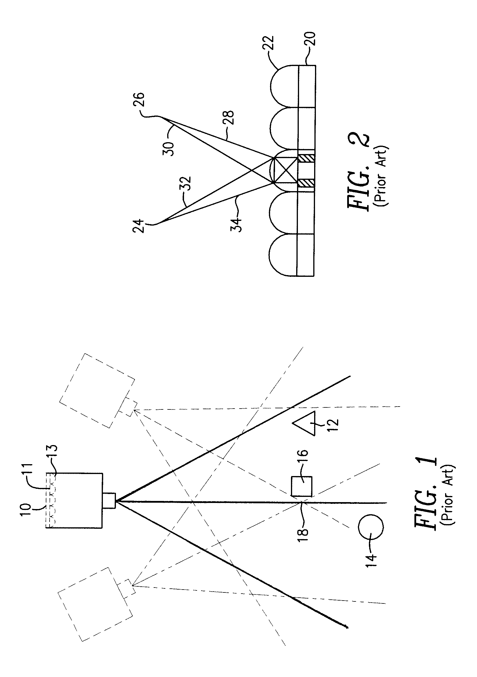
[0016]Typical prior art cameras for obtaining stereographic photographs are well known and are schematically indicated in prior art FIG. 1. They generally comprise a standard commercial camera 10 mounted on a suitable non-illustrated structure for traversing a path about one or more subject images 12, 14 and 16, film 11, and an overlying lenticular screen 13. As shown in FIG. 1, camera 10 is capable of being moved between dotted-line positions along an arc whose radii intersect at point 18, the central point of any particular picture to be taken. The different relative positions of the camera while photographing the object, or the difference in point of view, i.e., parallax, of the camera as it traverses its arc is illustrated by the rays extending, from each of the cameras. The relative rays are designated by dotted lines with respect to the left position of the camera, by solid lines with respect to the central position of the camera, and by dash lines with respect to the right po...


PUM


Abstract

The present invention provides an advance in multi-dimensional displays for digital monitors and televisions. In general, the present invention provides image capture devices arranged at different angles about a target image, or in a straight line, to capture images at pre-designated angles. Each captured image is combined into a composite image using hardware such as a computer. The composite image and a virtual lens are then transmitted together to a display means to be viewed having stereoscopic characteristics.

Description

PRIORITY AND RELATED APPLICATION[0001]N / a.FIELD OF THE INVENTION[0002]This invention generally relates to a novel virtual lens for transmitting stereoscopic images and specifically concerns novel techniques and apparatus for viewing such images for use with flat screen televisions, computer displays, fluoroscopes and other imaging electronic recording and imaging devices, either analog or digital, providing an illusion of depth to the viewer.BACKGROUND OF THE INVENTION[0003]Many of the modern day techniques use lenticulated images to create stereoscopic images. These techniques are limited in that they require the use of a lenticular viewing lens to visualize the stereoscopic image. In general, stereoscopic photographs of an object can be made by exposing a photographic film record through a lenticular screen with attendant relative movement between the camera lens, the object, and / or the film to provide a lenticulated or strip-like base image, each strip-like image being representa...

Claims


Application Information

Patent Timeline
Patent Type & Authority Applications(United States)
IPC IPC(8): H04N13/02H04N13/229H04N13/395
CPCH04N13/0228H04N13/0495H04N13/0242H04N13/395H04N13/243H04N13/229
Inventor HOPPENSTEIN, REUBEN
Owner 3 D VIRTUAL LENS TECH
Why Eureka
Try Eureka