Audio transform coding using pitch correction

a technology of pitch correction and audio transform, applied in the field of audio processors, can solve the problems of reducing coding efficiency, difficult synchronization, and difficult for applications with limited coding delay, and achieve the effects of reducing the transition length (samples), preserving the capability of overlap, and efficient coded

Active Publication Date: 2010-08-05
FRAUNHOFER GESELLSCHAFT ZUR FOERDERUNG DER ANGEWANDTEN FORSCHUNG EV
View PDF20 Cites 44 Cited by
  • Summary
  • Abstract
  • Description
  • Claims
  • Application Information

AI Technical Summary

Benefits of technology

[0023]As the sampling rates of the two overlapping blocks may be different (different values of the underlying audio signals correspond to identical samples), the same number of samples may now correspond to different portions of the signal (signal shapes). However, the previous requirement may be fulfilled by reducing the transition length (samples) for a block with a lower-effective sampling rate than its associated overlapping block. In other words, a transform window calculator or a method to calculate scaling windows may be used, which provides scaling windows with an identical number of samples for each input block. However, the number of samples used to fade out the first input block may be different from the number of sampl...

Problems solved by technology

For signals with varying pitch, however, the energy corresponding to each harmonic component is spread over several transform coefficients, thus, leading to a reduction of coding efficiency.
This would make applications with limited coding delay nearly impossible and, furthermore, would result in difficulties in synchronization.
However, this is achieved by introducing undesirable constraints to the applicable warp contours applicable.
In MDCT, applying the forward and the backward transform to one input block does, however, not lead to its full reconstruction as,...

Method used


Image

  • Audio transform coding using pitch correction
  • Audio transform coding using pitch correction
  • Audio transform coding using pitch correction

Examples


Embodiment Construction

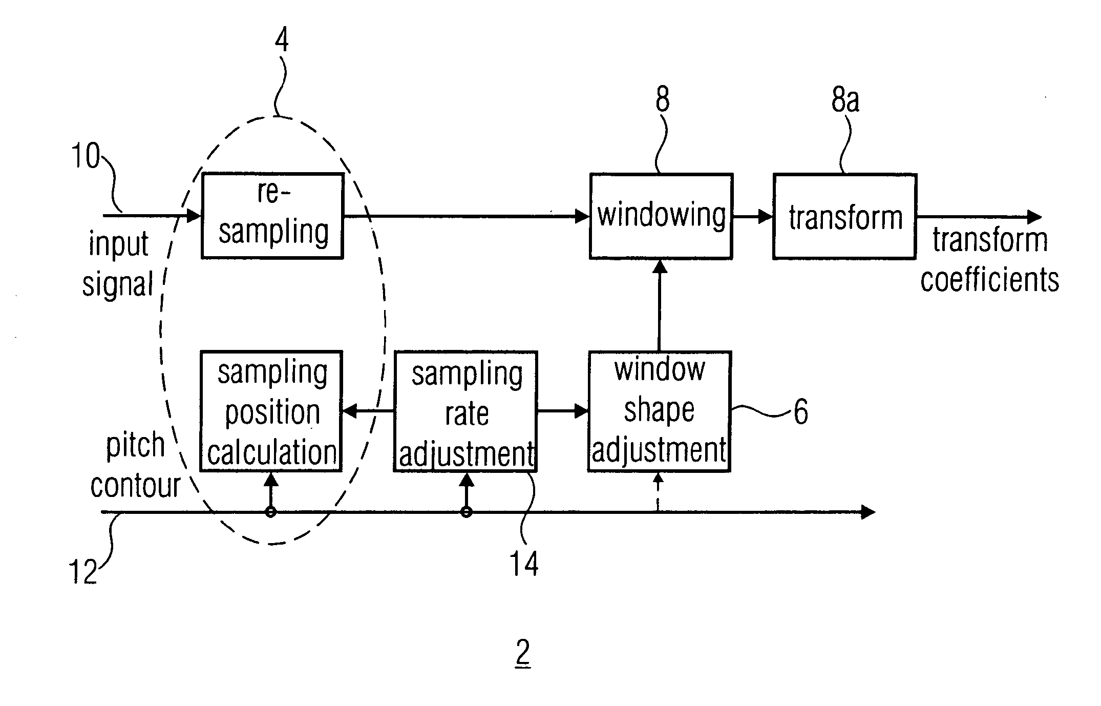
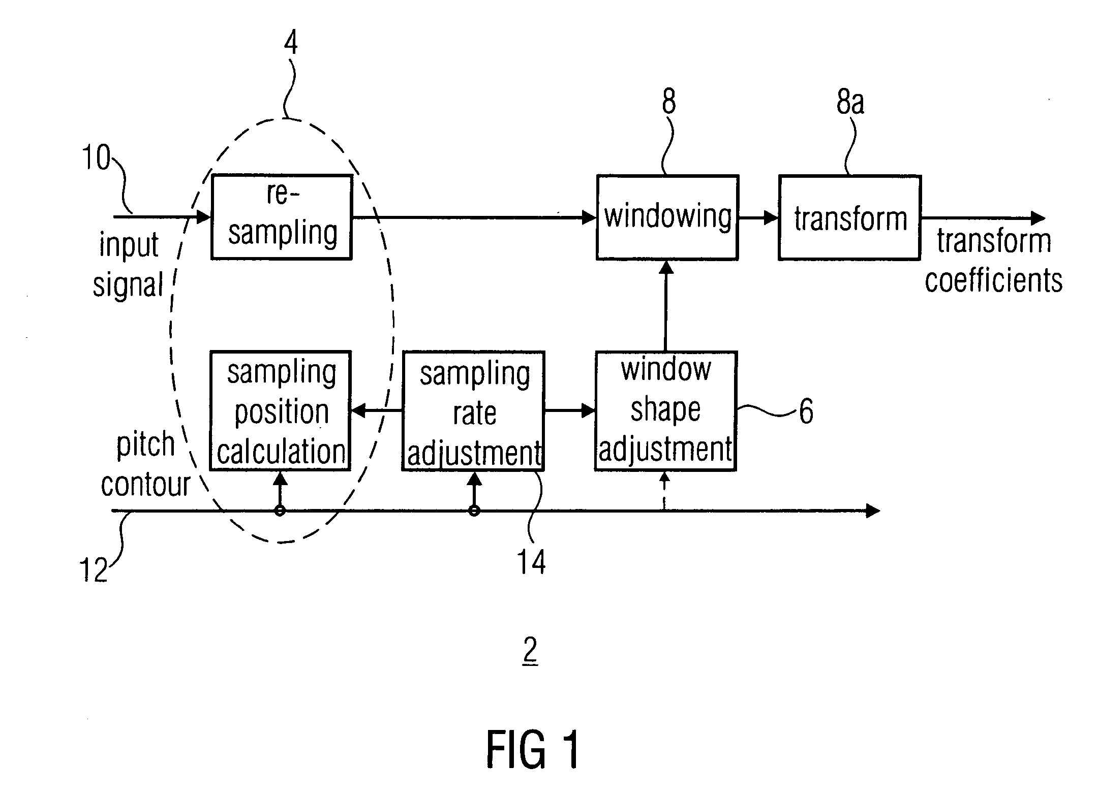
[0043]FIG. 1 shows an embodiment of an audio processor 10 (input signal) for generating a processed representation of an audio signal having a sequence of frames. The audio processor 2 comprises a sampler 4, which is adapted to sample an audio signal 10 (input signal) input in the audio processor 2 to derive the signal blocks (sampled representations) used as a basis for a frequency domain transform. The audio processor 2 further comprises a transform window calculator 6 adapted to derive scaling windows for the sampled representations output from the sampler 4. These are input into a windower 8, which is adapted to apply the scaling windows to the sampled representations derived by sampler 4. In some embodiments, the windower may additionally comprise a frequency domain transformer 8a in order to derive frequency-domain representations of the scaled sampled representations. These may then be processed or further transmitted as an encoded representation of the audio signal 10. The a...


PUM


Abstract

A processed representation of an audio signal having a sequence of frames is generated by sampling the audio signal within first and second frames of the sequence of frames, the second frame following the first frame, the sampling using information on a pitch contour of the first and second frames to derive a first sampled representation. The audio signal is sampled within the second and third frames, the third frame following the second frame in the sequence of frames. The sampling uses the information on the pitch contour of the second frame and information on a pitch contour of the third frame to derive a second sampled representation. A first scaling window is derived for the first sampled representation, and a second scaling window is derived for the second sampled representation, the scaling windows depending on the samplings applied to derive the first sampled representations or the second sampled representation.

Description

BACKGROUND OF THE INVENTION[0001]Several embodiments of the present invention relate to audio processors for generating a processed representation of a framed audio signal using pitch-dependent sampling and re-sampling of the signals.[0002]Cosine or sine-based modulated lapped transforms corresponding to modulated filter banks are often used in applications in source coding due to their energy compaction properties. That is, for harmonic tones with constant fundamental frequencies (pitch), they concentrate the signal energy to a low number of spectral components (sub-bands), which leads to efficient signal representations. Generally, the pitch of a signal shall be understood to be the lowest dominant frequency distinguishable from the spectrum of the signal. In the common speech model, the pitch is the frequency of the excitation signal modulated by the human throat. If only one single fundamental frequency would be present, the spectrum would be extremely simple, comprising the fun...

Claims


Application Information

Patent Timeline
IPC IPC(8): G10L19/02
CPCG10L19/022G10L19/0212
Inventor EDLER, BERNDDISCH, SASCHAGEIGER, RALFBAYER, STEFANKRAEMER, ULRICHFUCHS, GUILLAUMENEUENDORF, MAXMULTRUS, MARKUSSCHULLER, GERALDPOPP, HARALD
Owner FRAUNHOFER GESELLSCHAFT ZUR FOERDERUNG DER ANGEWANDTEN FORSCHUNG EV
Why Eureka
Try Eureka