Multistage Hydraulic Gas Compression/Expansion Systems and Methods

a gas compression/expansion system and multi-stage technology, applied in the direction of electrical storage system, rotary clutch, fluid coupling, etc., can solve the problems of low pressure rating and conversion efficiency of this conversion system, inefficient for most energy applications, and difficulty in realizing an isothermal process. achieve the effect of easing the automatic control of the valv

Active Publication Date: 2010-08-12
ECOLE POLYTECHNIQUE FEDERALE DE LAUSANNE (EPFL)
View PDF4 Cites 47 Cited by
  • Summary
  • Abstract
  • Description
  • Claims
  • Application Information

AI Technical Summary

Benefits of technology

[0025]Several air and liquid valves operated by a common camshaft are used to control the compression / expansion and transfer of the two fluids from one enclosure to the other. Several pressure-controlled air valves are also used to operate the system in a variable stage configuration. The different parts are arranged in such a way to form a single compact embodiment and to ease the automatic control of the valve and the drive of the external heat exchanger's fan.

Problems solved by technology

Since it is difficult to realise an isothermal process in these work-chambers, the compression / expansion process is subdivided into several stages and heat exchangers are inserted in between.
However, given the difficulties to implement a good heat exchange in the compression / expansion chambers, and the important leakage and friction related to the gaseous nature of air, the pressure ratings and conversion efficiency of this conversion system remain low and make it inefficient for most energy applications.
One of the main challenges in using hydraulic systems to compress / expand air is the liquid-to-air interface.
However, good heat exchange will require a high density of plate, which is not easy to realise.
In addition, these hydro-pneumatic systems are somewhat bulky as they are assemblages of several distinct components and machines.
Moreover, these split topologies require many ancillary devices for the command and control of the system's operation.

Method used


Image

  • Multistage Hydraulic Gas Compression/Expansion Systems and Methods
  • Multistage Hydraulic Gas Compression/Expansion Systems and Methods
  • Multistage Hydraulic Gas Compression/Expansion Systems and Methods

Examples


Embodiment Construction

[0047]Constitution of the First Inventive System (System 1)

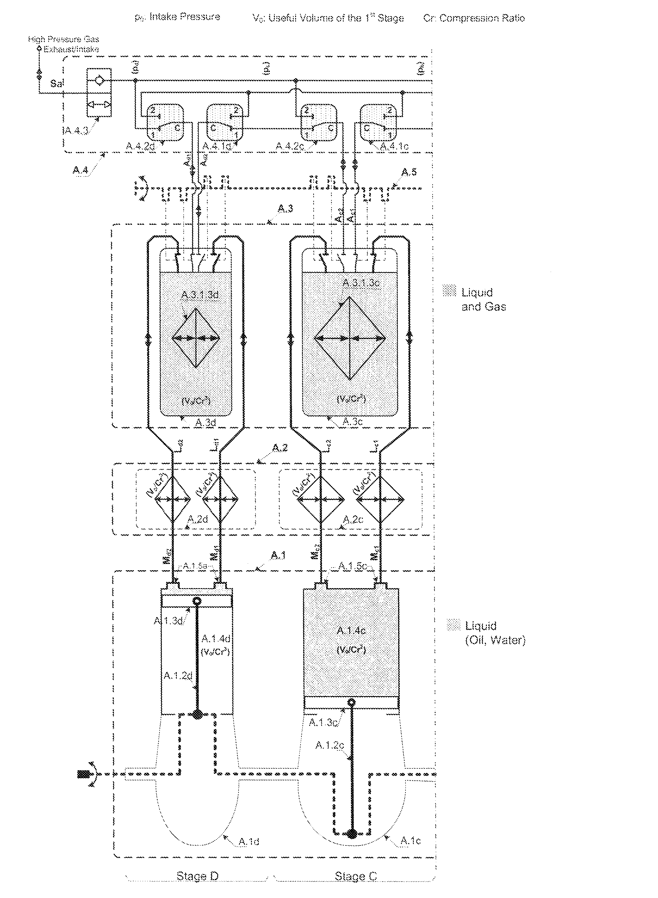
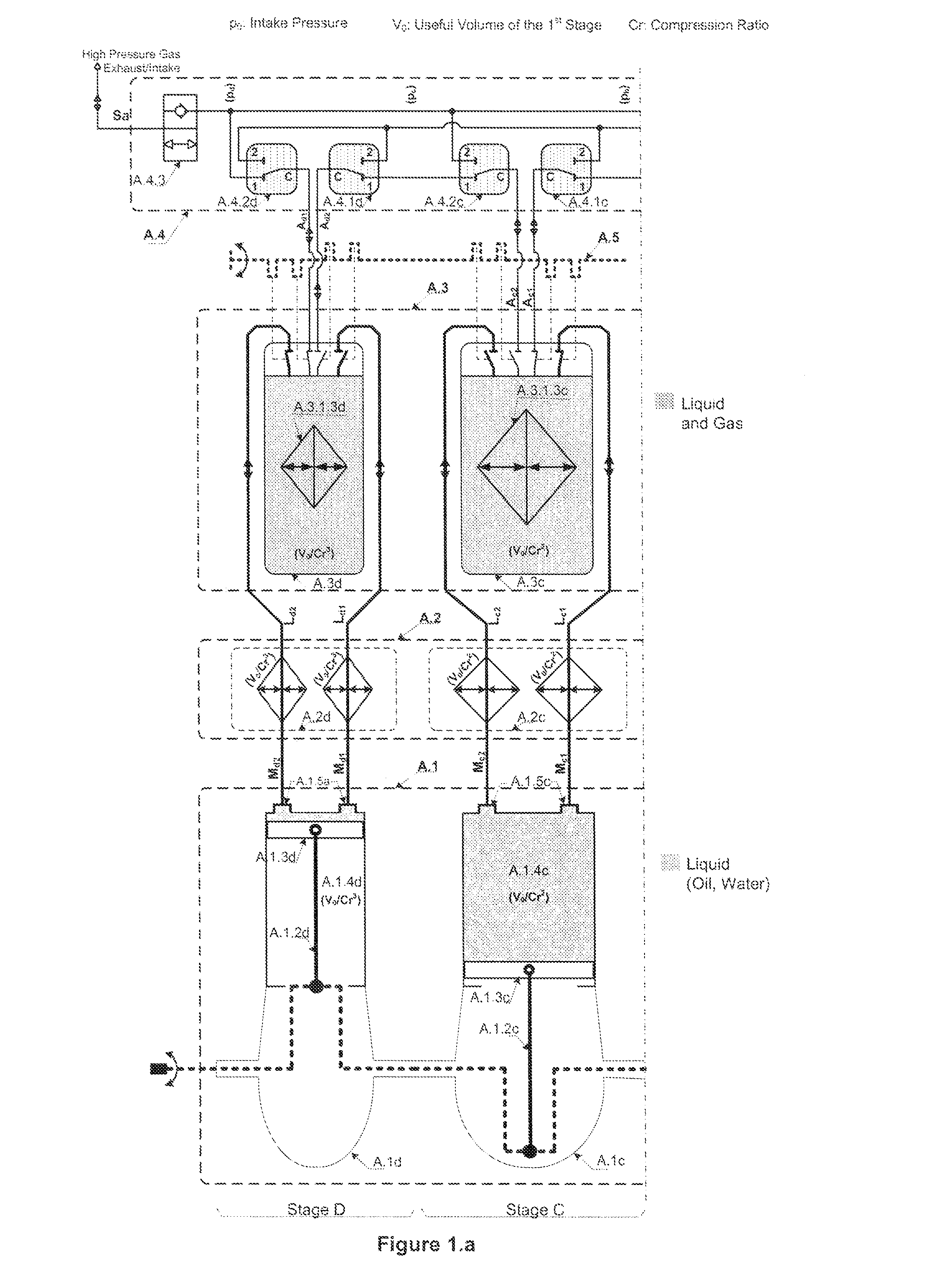
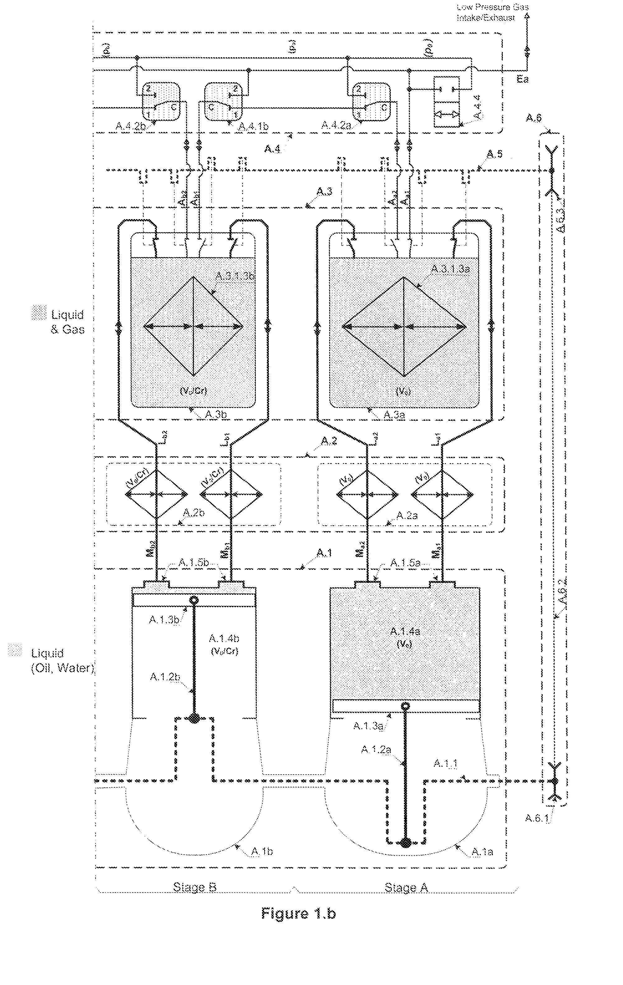
[0048]The machine according to the invention is made of 6 main parts as illustrated in FIG. 1:[0049]A special multi-circuit multi-displacement hydraulic piston motor / pump A.1.[0050]A multistage multi-circuit heat exchanger A.2 made of several 2-circuit heat exchange stages A.2a to A.2d. [0051]A multistage multi-capacity hydraulic gas compression / expansion unit A.3 with integrated heat exchanger.[0052]A multistage gas directional control unit A.4 made of several directional valve for controlling the gas flow direction between the compression / expansion modules and the main system's gas intake / exhaust port Ea and Sa.[0053]A common camshaft A.5 for controlling the gas and hydraulic valves of all the compression / expansion modules.[0054]A mechanical transmission line A.6 for transmitting mechanical power among units if necessary.

[0055]The Multistage Hydraulic Gas Compression / Expansion Unit

[0056]The illustrated compression-expansio...


PUM


Abstract

Multistage hydraulic systems and methods for converting the potential energy of a pressurized gas, particularly air, into mechanical work when operating in motor, and for producing compressed gas from the mechanical work of the rotating shaft when rotating when operating in compressor mode, by performing a successive expansion / compression of the said gas. Each of the systems comprises: a multistage Compression-Expansion Unit made of several hydraulic Compression-Expansion Modules having different capacity and integrating a gas / liquid separating heat exchanger, designed to convert pressure power into a hydraulic power and vice-versa, by performing an essentially isothermal compression / expansion of the gas; a single stage or multistage, direct or indirect, external forced-air Heat Exchanger for maintaining the active liquid at ambient temperature; and a multi-circuit, multi-displacement Hydraulic Motor / Pump for converting hydraulic power into mechanical power and vice-versa.

Description

FIELD OF THE INVENTION[0001]This invention concerns methods of efficiently producing high pressure gas and of converting the potential energy of pressurized gas into mechanical work and vice-versa, as well as reversible, self-controlled hydraulic systems, which directly convert the pressure energy of compressed gas, particularly air, into mechanical work and vice-versa, by performing successive high efficiency compression / expansion.BACKGROUND OF THE INVENTION[0002]A list of the references quoted in this section is given at the end of the Description.[0003]This invention is related to the production of high pressure air to be used for breathing purposes (medical, diving, etc) or as power source or power transmission for various air-powered tools and industrial processes. It is also related to the use of compressed air as energy storage media like in the case of compressed-air-powered cars or for example to circumvent the intermittency of some renewable energy sources such as solar an...

Claims


Application Information

Patent Timeline
Patent Type & Authority Applications(United States)
IPC IPC(8): F15B1/02
CPCF01B17/02F01B17/025F04F1/10H02J15/006F01K7/36F01K27/005H02J15/003F01K7/025
Inventor LEMOFOUET, SYLVAINRUFER, ALFRED
Owner ECOLE POLYTECHNIQUE FEDERALE DE LAUSANNE (EPFL)
Why Eureka
Try Eureka