Shade wing

a technology of aerodynamic wings and wings, which is applied in the direction of rod connections, cycle equipment, transportation and packaging, etc., can solve the problems of decreasing the efficiency of vehicles, and achieve the effect of less drag and easy propulsion

Inactive Publication Date: 2010-08-12
FORESTER WALTER
View PDF12 Cites 6 Cited by
  • Summary
  • Abstract
  • Description
  • Claims
  • Application Information

AI Technical Summary

Benefits of technology

[0014]The present invention diverges from the previous art by providing the rider of the bicycle

Problems solved by technology

While forming an excellent cover for the rider it is at the expense of weig

Method used


Image

  • Shade wing
  • Shade wing
  • Shade wing

Examples


Embodiment Construction

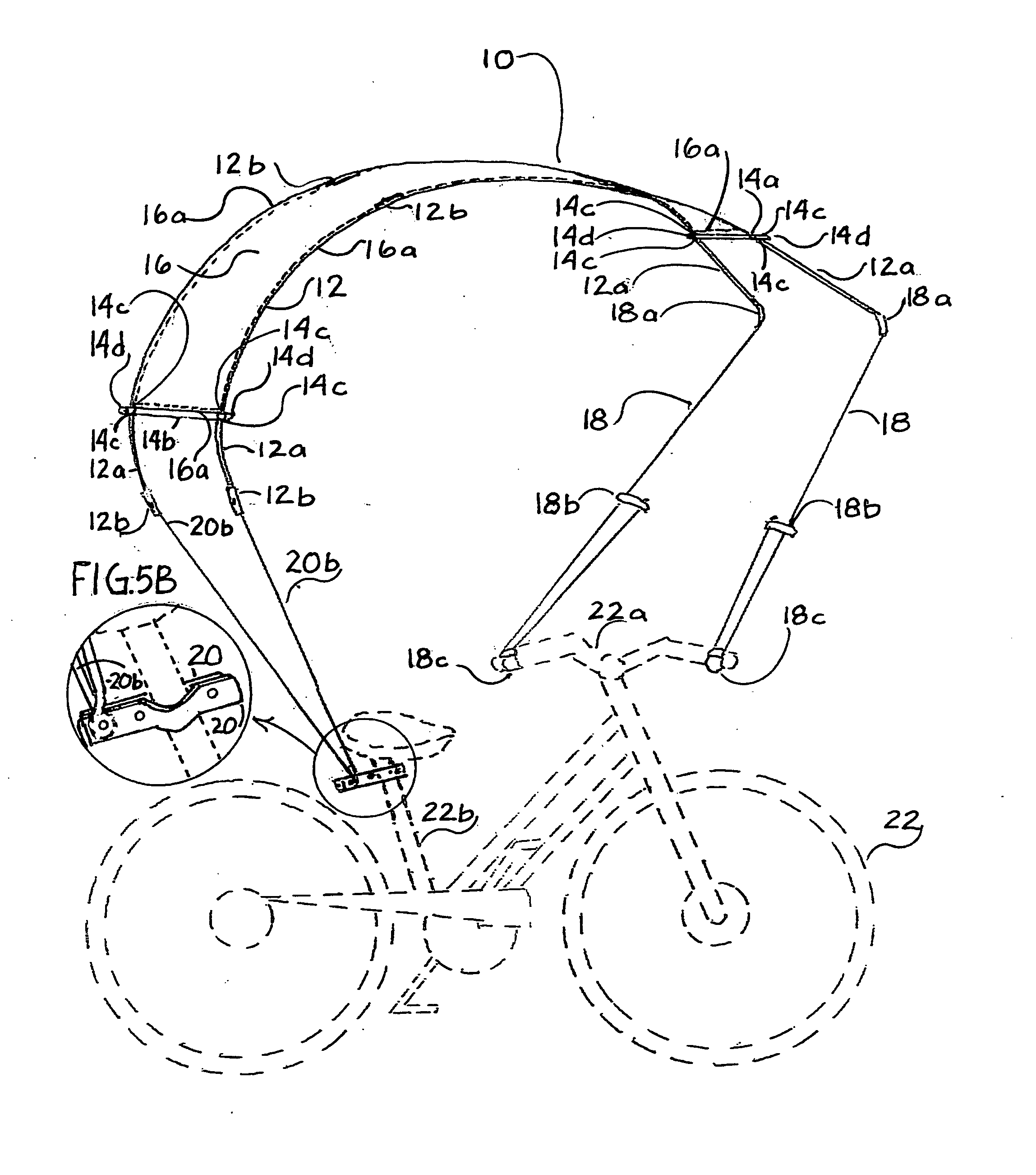
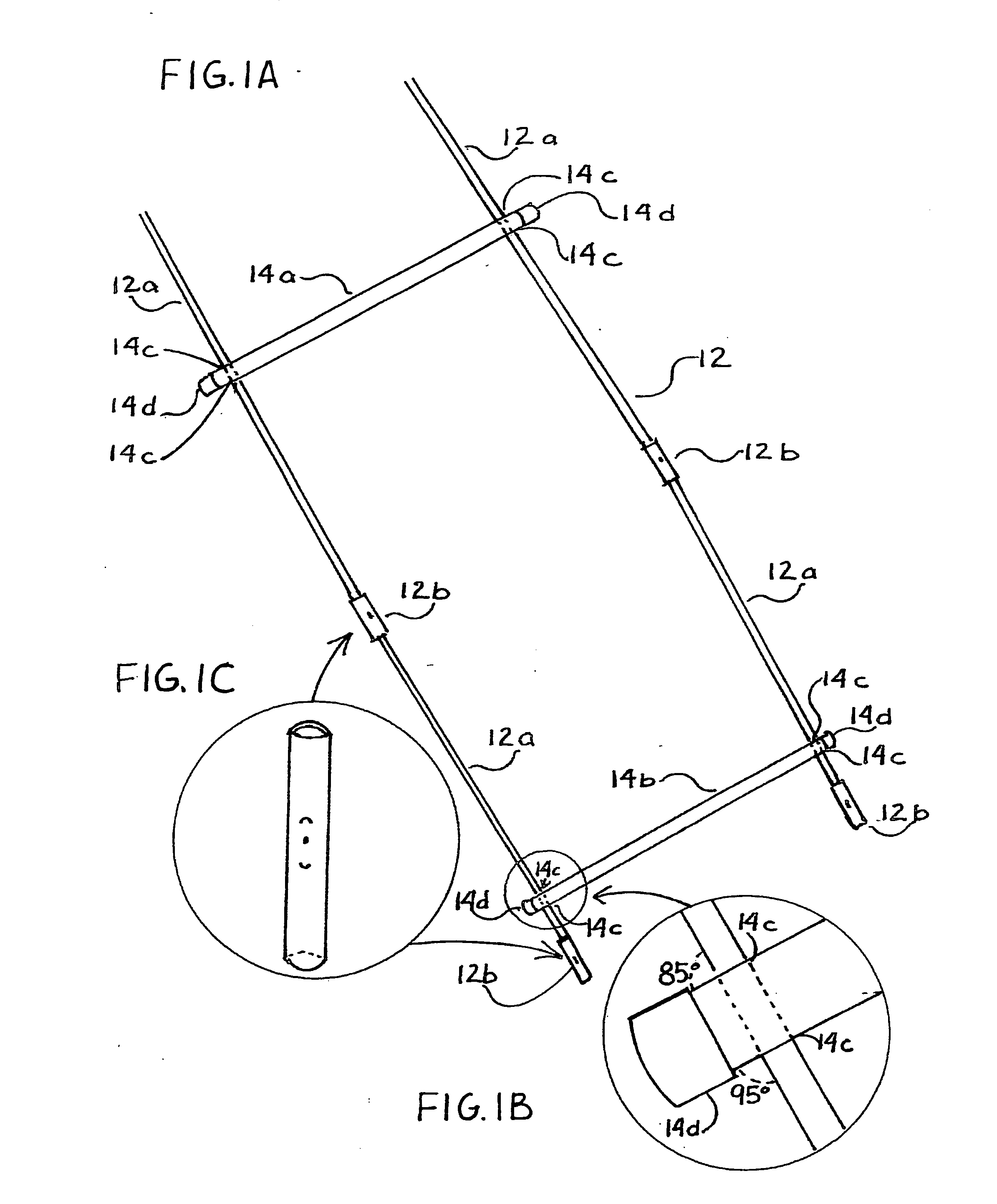
[0046]With reference now to the drawings and in particular to FIG. 1A thereof, the preferred embodiment of the shade wing embodying the principles and concepts of the present invention and generally designated by the reference numeral 10 will be described.

[0047]The present invention, the shade wing 10 is comprised of a plurality of components. Such components in their broadest context include a frame, leading edge shade wing frame control cables, a wing cover and a device for attaching the shade wing frame to any bicycle or tricycle. Such components are individually configured and correlated with respect to each other so as to attain the desired objective.

[0048]First provided is a bicycle 22. The bicycle has handlebars 22a. The bicycle has a seat post 22b.

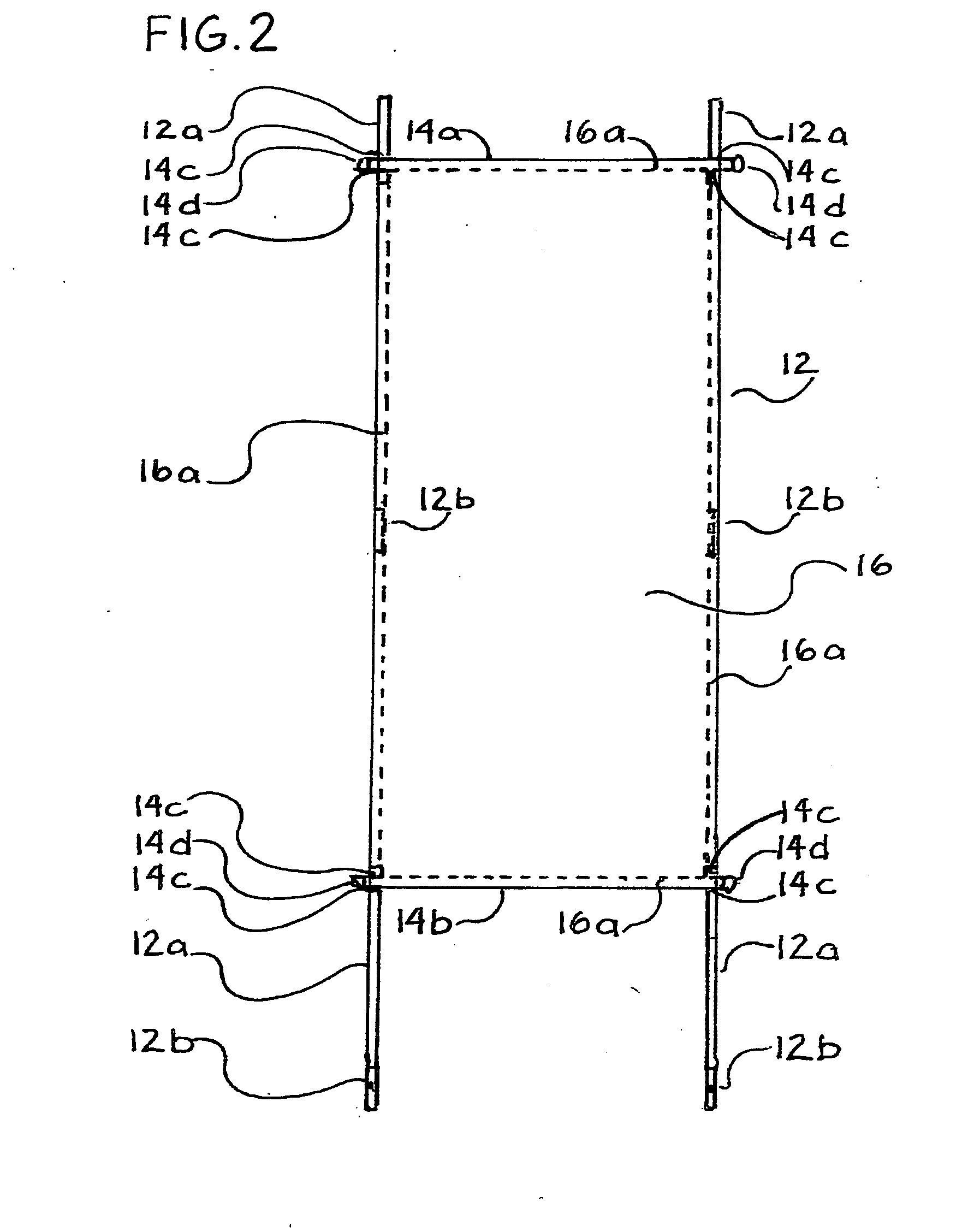
[0049]The shade wing begins with a frame FIG. 1A and a frame cover FIG. 2 Ref. No. 16. The frame is constructed as follows: four ¼ inch outside diameter by 30 inches in length fiberglass wing ribs 12a coupled by two ¼ inch by 2 in...


PUM


Abstract

A rectangular wing formed by two parallel fiberglass ribs, tubular leading edge and tubular trailing edge with a nylon cover. The attack angle of the leading edge is controlled by the rider of the bicycle or tricycle giving lift to the wing. This lift assists in the support of the wing allowing for lighter wing ribs to be used in the construction. The lighter construction and reduced wind resistence increases the efficiency of the bicycle or tricycle using less human effort for propulsion while providing protection from sun and light rain.

Description

CROSS-REFERENCE TO RELATED APPLICATIONS [0001]Provisional Application No. 61 / 151,050[0002]I claim the benefit of the first filing date Feb. 9, 2009[0003]Filed: Feb. 9, 2009STATEMENT REGARDING FEDERALLY SPONSORED RESEARCH OR DEVELOPMENT [0004]Not ApplicableREFERENCE TO SEQUENCE LISTING, A TABLE, OR A COMPUTER PROGRAM LISTING COMPACT DISC APPENDIX [0005]Not ApplicableRELATED APPLICATION [0006]The present U.S. Non-provisional Patent Application is based upon U.S. Provisional Patent Application No. 61 / 151,050 filed Feb. 9, 2009, the subject matter of which is incorporated herein by reference.BACKGROUND OF THE INVENTION[0007](1) Field of the Invention[0008]The present invention relates to an aerodynamic wing protecting a rider of a bicycle or tricycle from sun and light rain, without appreciably increasing weight or drag (wind resistence).[0009](2) Description of Prior Art[0010]Many designs and configurations exist in the prior art. The use of fixed supports to maintain a cover over a ...

Claims


Application Information

Patent Timeline
IPC IPC(8): E04H15/06F16B9/00
CPCY10T403/33B62J17/08
Inventor FORESTER, WALTER
Owner FORESTER WALTER
Why Eureka
Try Eureka