Log debarking tool and tool tip

a tool tip and debarking technology, applied in the field of debarking machines, can solve the problems of affecting the removal and replacement of bolts, and affecting the removal and replacement process of tool tips, so as to achieve the effect of high debarking ra

Active Publication Date: 2010-08-12
REIMLER JAMES L
View PDF12 Cites 1 Cited by
  • Summary
  • Abstract
  • Description
  • Claims
  • Application Information

AI Technical Summary

Benefits of technology

[0028]Another alternative would be to form the tool tip as a two piece tip with one attachment leg that attaches from the front of the tool and a rear leg with the debarking edge attached and protruding only...

Problems solved by technology

The blade tip is positioned in such a way that it is difficult to remove and replace, because the attachment bolts are positioned on the side of the blade perpendicular to the longitudinal axis of movement of the log through the rotating tools.
For this reason, the tools adjacent to the tool whose tip is being removed and replaced interfere with pr...

Method used


Image

  • Log debarking tool and tool tip
  • Log debarking tool and tool tip
  • Log debarking tool and tool tip

Examples


Embodiment Construction

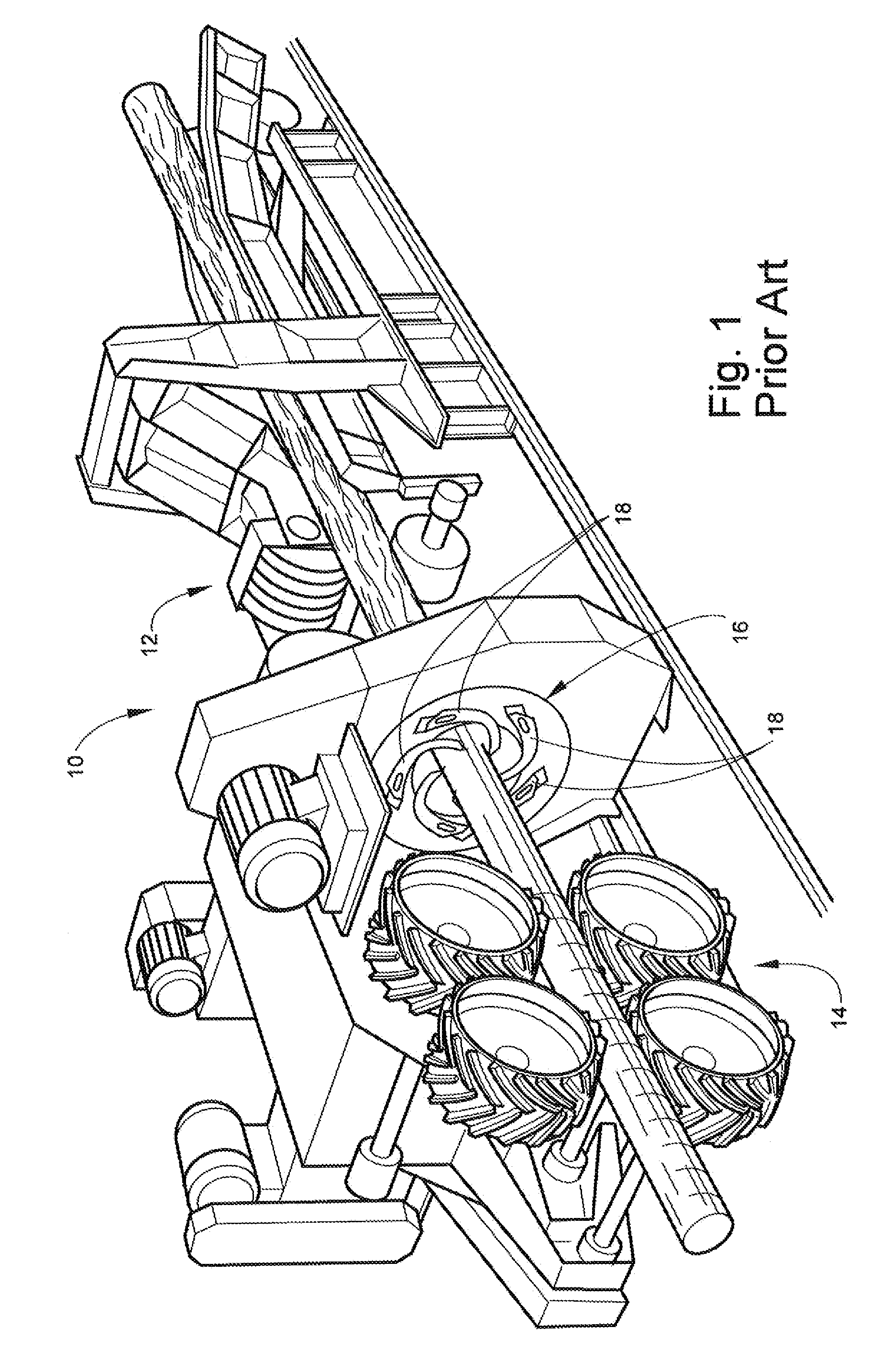
[0020]Referring now to the drawings, FIG. 1 illustrates a ring-rotor debarker 10 of the general type with which the novel debarking tool and tool tip may be used. The debarker 10 includes an infeed conveyor assembly 12 and feed roll assembly 14, the exact type and design of which are not relevant to the invention. A ring rotor 16 is positioned between the infeed conveyor assembly 12 and the feed roll assembly 14. Prior art ring rotors such as ring rotor 16 include tools 18 that are positioned in a spiral orientation and past which logs move to be debarked, as shown in FIG. 1.

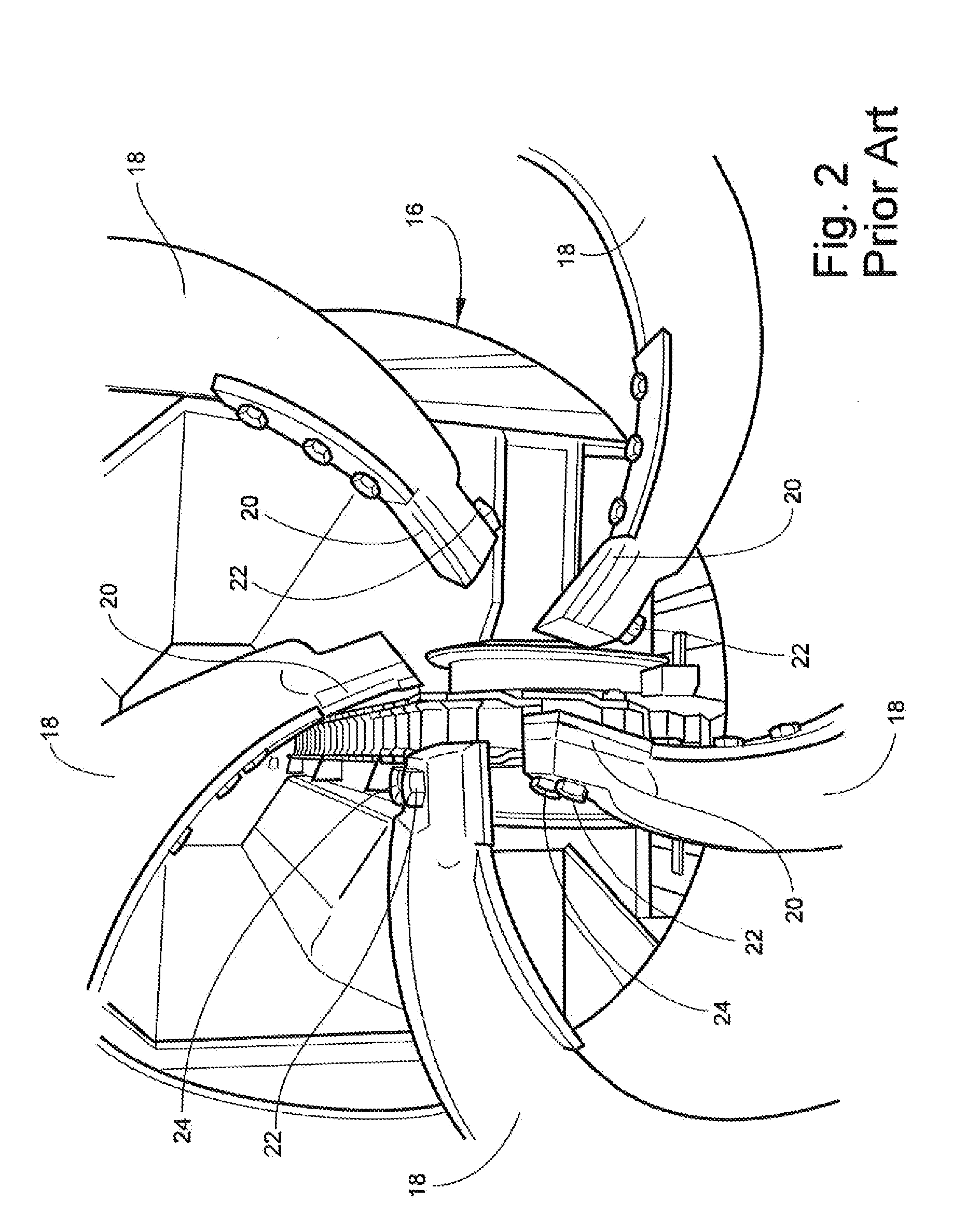
[0021]As shown more clearly in FIG. 2, the tools 18 include respective tips 20. These tips 20 are removable by means of bolts 22, 24, which extend generally perpendicular to the axis of movement of the log through the debarker 10. This arrangement means that the bolts 22, 24 must be approached from the side, rather than from a more efficient “straight-on” position. As can be seen in FIG. 2, the tool 18 adjacent ...


PUM


Abstract

A tool for a ring-rotor log debarker, including an elongate, curved body for being attached by one end to a ring rotor of a log debarker. At least one attachment hole extends through the curved body of the tool on a free end opposite the one end attached to the ring rotor, and communicates with the first and second upstream and downstream oriented surfaces. A tip is placed onto the free end of the tool body, and includes an attachment hole sized and positioned for alignment with the at least one attachment hole in the tool body and for receiving a bolt through the aligned attachment holes for securing the tip to the tool body.

Description

TECHNICAL FIELD AND BACKGROUND OF THE INVENTION[0001]This invention relates to debarking machines generally referred to as “mechanical ring” debarkers. Debarkers of this type have a ring rotor into and through which successive logs are fed to be engaged and stripped of bark. More particularly, the invention is concerned with an improved debarking blade for mechanical ring debarking machines wherein the tip of the blade is designed so that it can be quickly and easily removed from the blade and replaced[0002]In debarking machines of the ring rotor type, several debarking tools are circularly arranged around the central opening of the rotor and extend generally radially inwardly with their cutting edges positioned adjacent to the axis of the rotor. As they are rotated by the ring rotor, the blades follow the periphery of the logs while the cutting tips remove the bark. When the rotor is rotated and a log is being fed into the rotor inlet, the leading butt end of the log engages the de...

Claims


Application Information

Patent Timeline
IPC IPC(8): B27L1/00
CPCB27L1/08
Inventor REIMLER, JAMES L.
Owner REIMLER JAMES L
Why Eureka
Try Eureka