Segmented packing ring

a packing ring and segment technology, applied in the direction of engine seals, pump components, liquid fuel engine components, etc., can solve the problems of uneven wear pattern of tangential ring, varying wear degree of radially and tangentially cut packing rings, and significant increase in leakage rate, so as to reduce the wear rate of packing rings

Inactive Publication Date: 2010-08-12
HOERBIGER KOMPRESSORTECHNIK HLDG GMBH
View PDF16 Cites 2 Cited by
  • Summary
  • Abstract
  • Description
  • Claims
  • Application Information

AI Technical Summary

Benefits of technology

[0006]The problem is solved according to the invention in that a number of first sealing segments, a number of second sealing segments, and a number of support segments are provided, wherein the support segments and the second sealing segments are arranged in an alternating successively abutting manner in the circumferential direction, and the first sealing segments are arranged in a manner axially abutting the second sealing segments and the support segments, and a nose extending axially is provided on the second sealing segments, which is arranged in the circumferential direction between two adjacent first sealing segments. Utilizing this arrangement of the segments it is achieved that the sealing segments are relieved by another segment, thus reducing the rate of wear of the packing ring. Furthermore, the material of the sealing segments available may be greatly utilized for the formation of wear in this manner.

Problems solved by technology

The radially and tangentially cut packing rings therefore show varying degrees of wear.
In addition to the circumstance that the tangentially cut ring always shows quicker wear due to the larger surface adjustment than the radially cut one, the tangential ring typically also has an uneven wear pattern in circumferential direction, which may be accompanied by an opening of the tangential cuts and therefore a significantly increased leakage.
In this manner such a ring may lose a large degree of the sealing effect thereof, even if the same has not yet reached the wear stop thereof (as opposed to the consumables compensation gap).
Furthermore, a packing ring combination made from radially and tangentially cut packing rings requires elastic deformations of the ring segments with increasing wear in order to be able to maintain the sealing effect.
Such a seal ring may therefore be subjected to a very high degree of wear without losing the sealing effect thereof.
For this purpose the rate of wear, apart from the pressures present, essentially only depends on the ring material or on the material combination of the ring / piston rod selected, and may therefore be very high such that the seal ring may show wear rather quickly.
The seal ring must therefore be exchanged in a timely manner before the sealing segments have too much wear, thus possibly resulting in damage or even destruction due to the mechanical and / or thermal stresses.
However, since the actual wear cannot be seen from the outside, the seal must be checked periodically, which is often also accompanied by a (premature) exchange of the seal rings.
The life of the seal rings is therefore possibly not optimally utilized.

Method used


Image

  • Segmented packing ring
  • Segmented packing ring
  • Segmented packing ring

Examples


Embodiment Construction

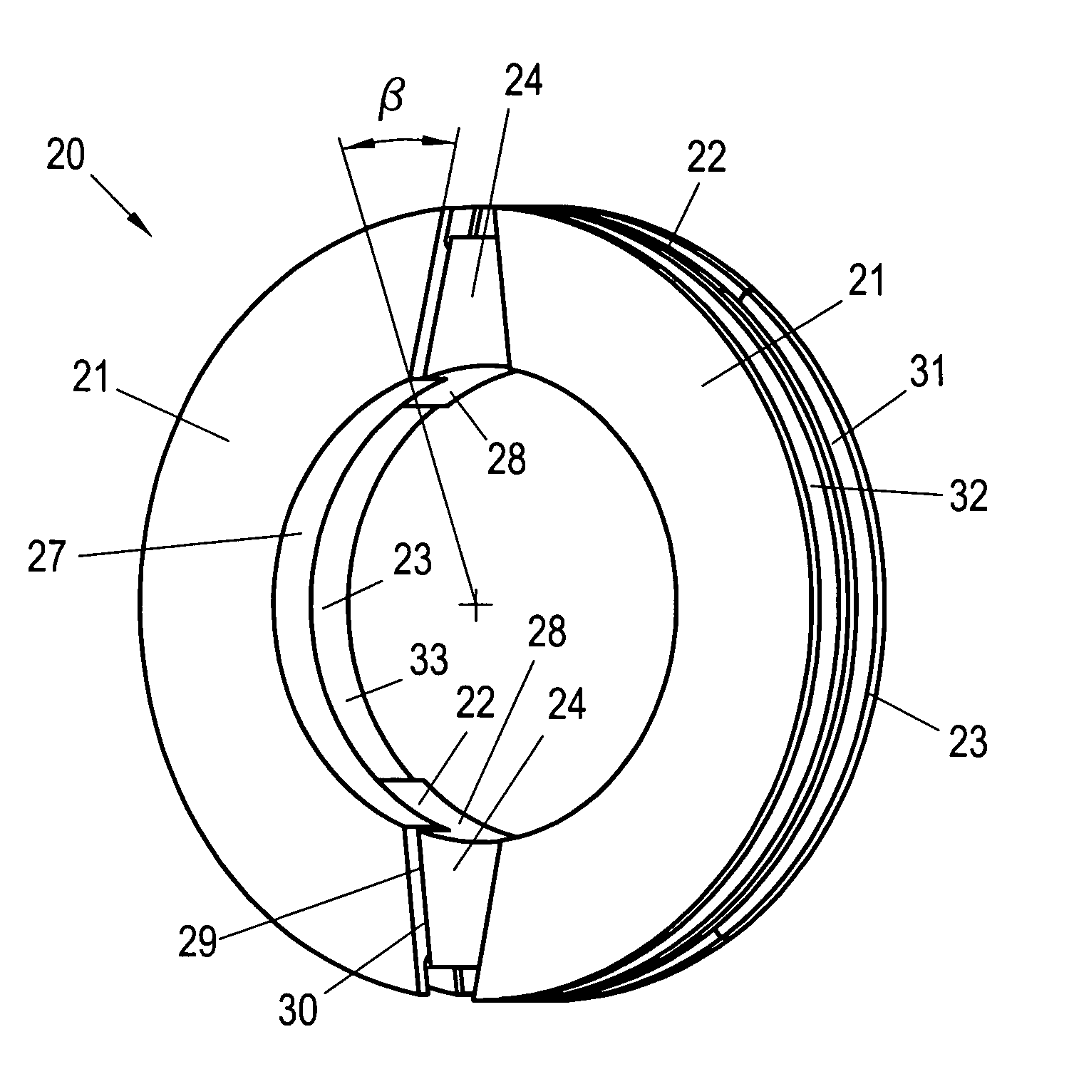
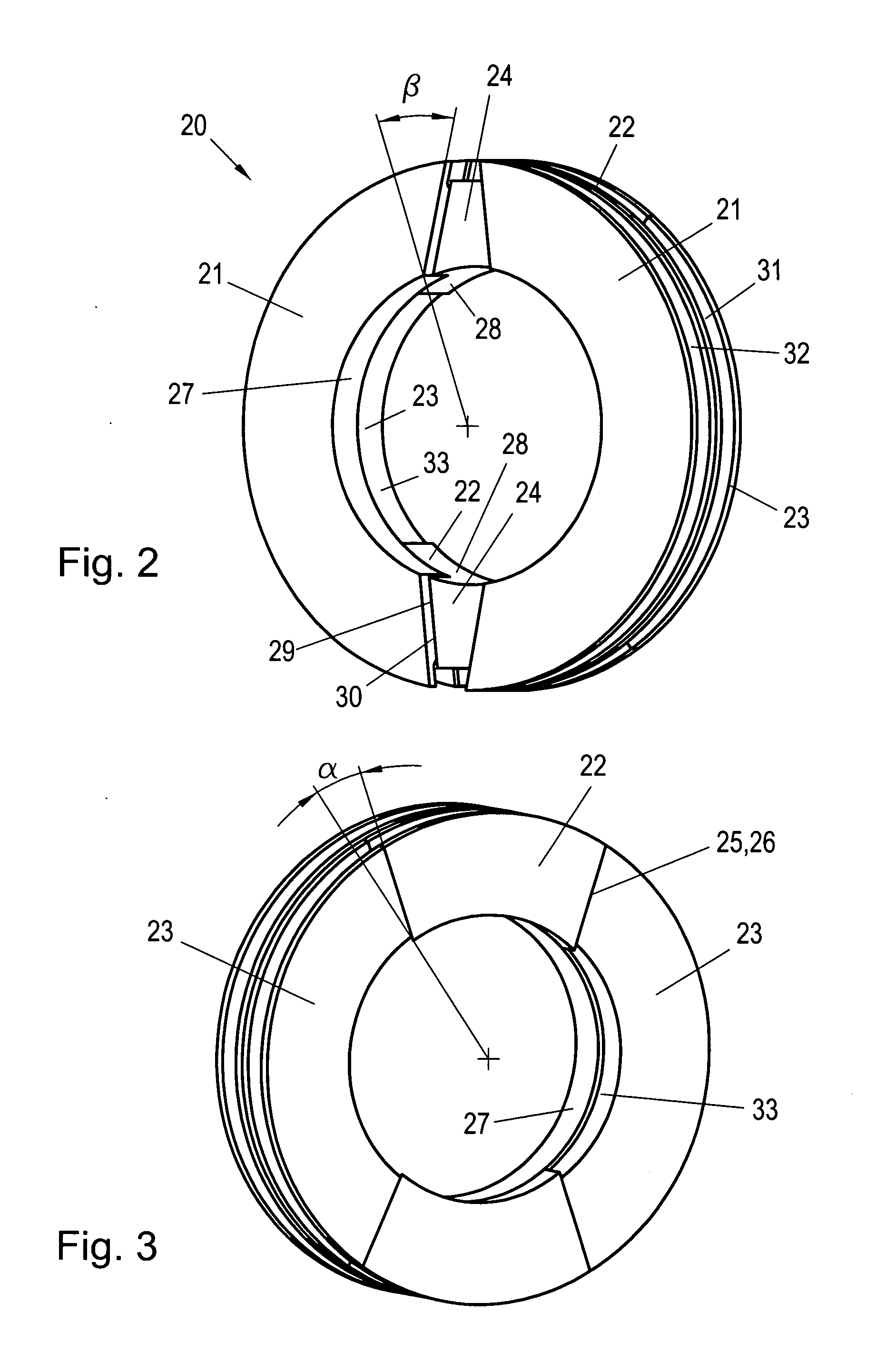
[0019]The perspective illustrations of a segmented packing ring 20 according to the invention in accordance with FIGS. 2 and 3 show the packing ring 20 from two different sides. The packing ring 20 consists of different ring segment-shaped segments, which together form the packing ring 20. Here, the packing ring 20 is formed from two first sealing segments 21, two second sealing segments 22, and two support segments 23. However, the packing ring 20 may also be embodied with more than two of the segments 21, 22, 23. The second sealing segments 22 and the support segments 23 abut each other in circumferential direction at the circumferential front surfaces 25, 26 thereof, wherein the support segments 23 and the second sealing segments are arranged in an alternating abutting manner. The first sealing segments 21 abut the second sealing segments 22 and the support segments 23 in an axial manner. Furthermore, an axial nose 24 is provided on the second sealing segments 22, which is arrang...


PUM


Abstract

A segmented packing ring 20 includes a number of first sealing segments 21, a number of second sealing segments 22, and a number of support segments 23, the support segments 23 and the second sealing segments 22 being arranged in an alternating successively abutting manner in the circumferential direction, and the first sealing segments 21 being arranged in a manner axially abutting the second sealing segments 22 and the support segments 23, and including a nose 24 extending axially on the second sealing segments 22, which is arranged in the circumferential direction between two adjacent first sealing segments 21.

Description

BACKGROUND OF THE INVENTION[0001]Piston compressors, particularly single-acting ones, require sealing along the oscillating piston rod 5. The sealing typically must be carried out against the (low) ambient pressure pu being present in the crankcase. Referring to FIGS. 1-3, the sealing elements being utilized in such a seal 4 are called packing rings 6, 7, and are arranged in a so-called pressure packing 2, usually consisting of a number of packing rings 6, 7, such as illustrated in FIG. 1 in a common design by way of example. For this purpose the sealing elements may follow inevitable lateral movements of the piston rod 5 without losing the sealing effect thereof. In order to increase life and reliability of a pressure packing 2, a plurality of such packing rings 6, 7 are switched in series in a pressure packing 2. For this purpose the packing rings 6, 7 may be arranged in the pressure packing 2 in a chamber disk 10. In order to prevent an extrusion of a packing ring 7 in the annula...

Claims


Application Information

Patent Timeline
Patent Type & Authority Applications(United States)
IPC IPC(8): F04B53/00F16J15/16
CPCF16J15/26
Inventor HOLD, CHRISTIANLINDNER-SILWESTER, TINOJANDL, ALEXANDER
Owner HOERBIGER KOMPRESSORTECHNIK HLDG GMBH
Why Eureka
Try Eureka