

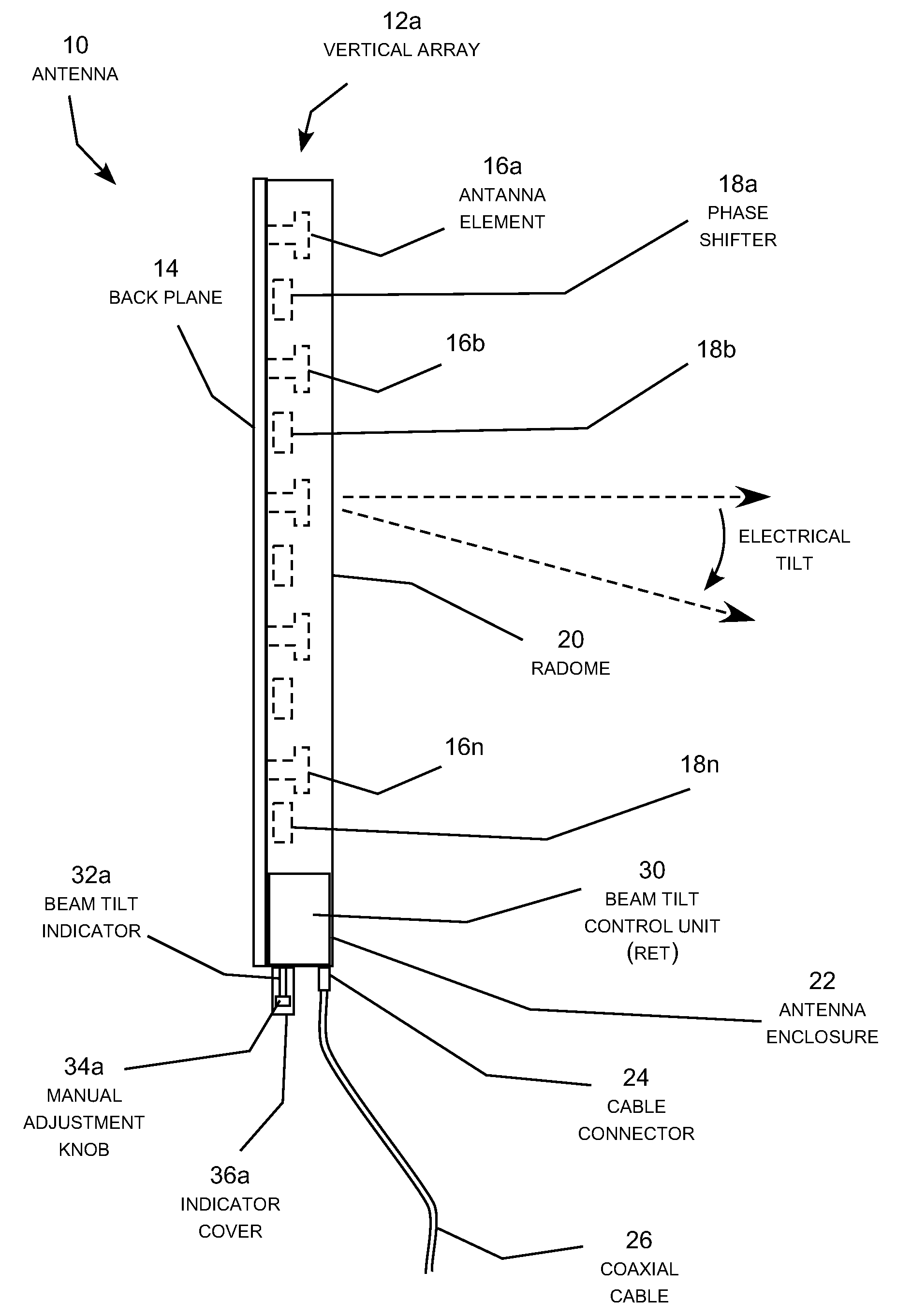
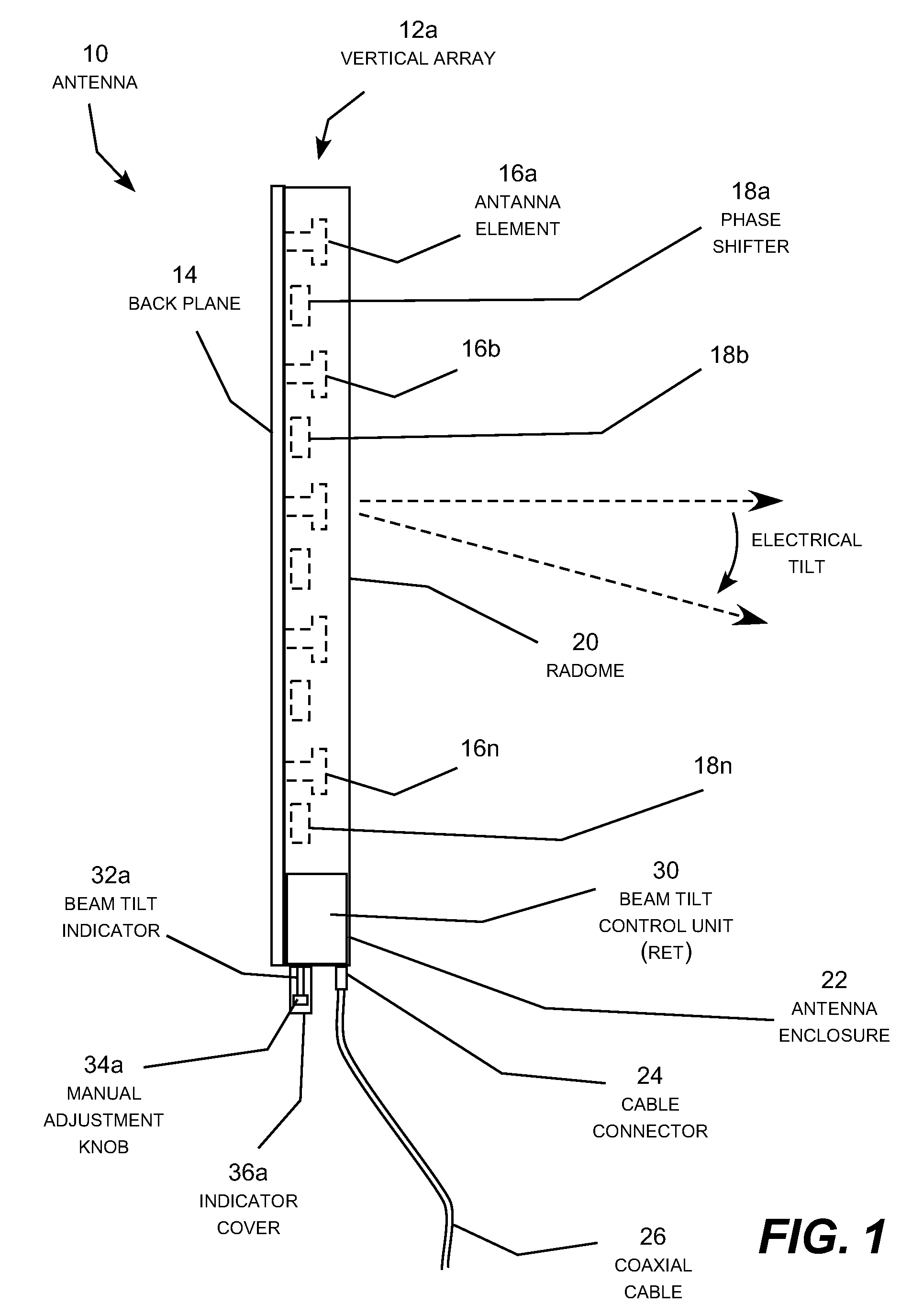
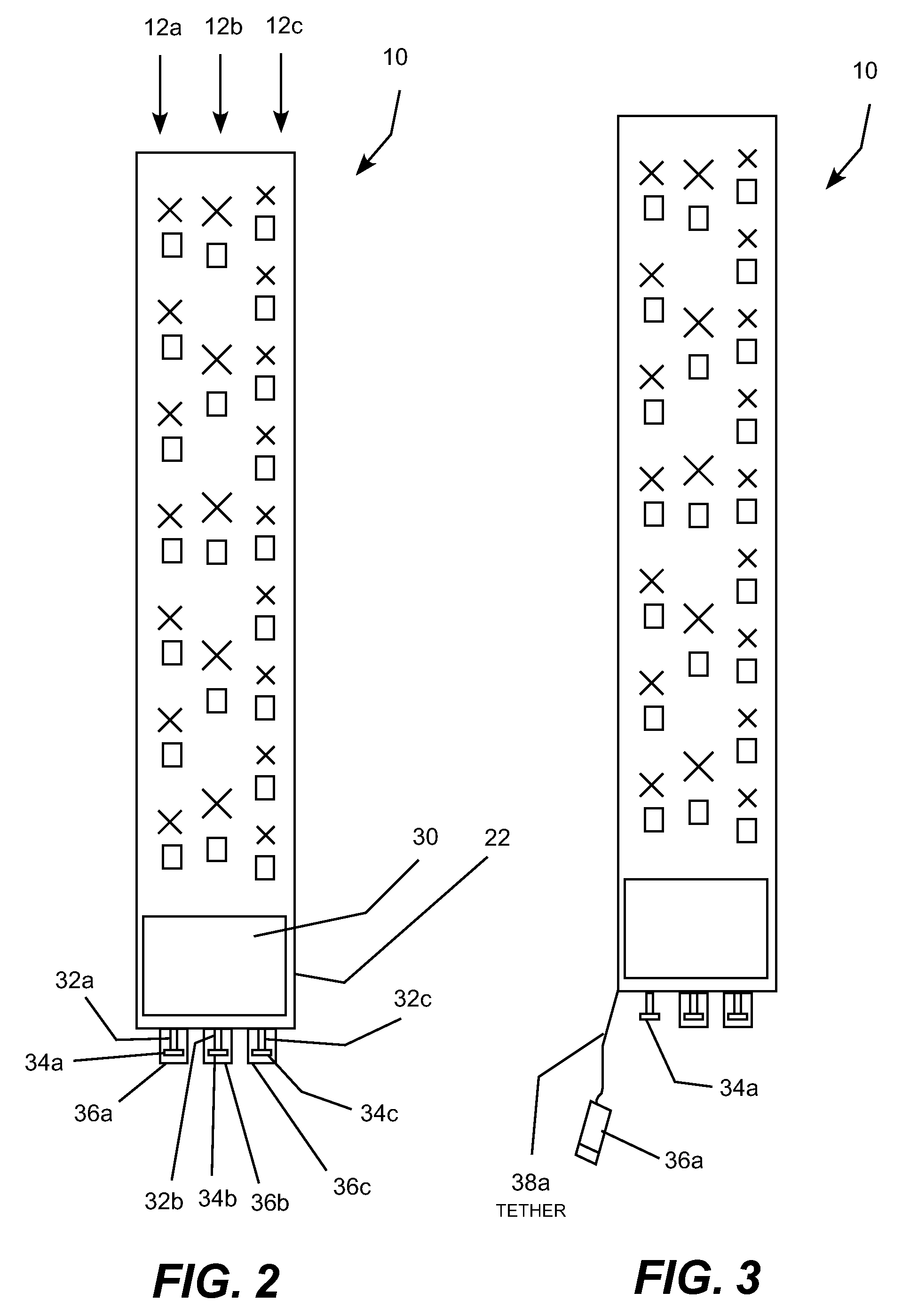
Remote electrical tilt antenna with motor and clutch assembly
a technology of clutch assembly and motor, which is applied in the direction of antennas, antenna details, radiating element housings, etc., can solve the problems of losing calibration between electromechanical actuator and antenna tilt setting, unable to manually adjust the tilt of the antenna, and unable to remove the actuator, etc., to achieve the effect of convenient manual turning of the phase shifter control knob
- Summary
- Abstract
- Description
- Claims
- Application Information
AI Technical Summary
Benefits of technology
Problems solved by technology
Method used
Image

Examples
Embodiment Construction
[0032]The present invention meets the need described above in a RET antenna with a motor and clutch assembly that is operative to mechanically disengage the DC motor and drive unit (also called the gear-motor unit) from the phase shifter adjustment shaft during a manual tilt operation. Disengaging the gear-motor unit removes the drag of the motor and the high gear ratio gear box from the phase shifter control rod making it easier to manually turn the phase shifter control knob. In addition, the clutch disengages the gear-motor without disengaging the position detector from the phase shifter control rod so that position calibration is not lost during manual tilt adjustment. When the manual tilt operation is completed, the mechanical tilt clutch enables the gear-motor unit to be reliably re-engaged with the phase shifter control rod for motorized electrical tilt operation without having to re-calibrate the position detector.
[0033]The mechanical tilt clutch incorporates a shaft positio...
PUM
 Abstract
Description
Claims
Application Information