
Heat actuated puncturing mechanism for a compressed gas cartridge

a technology of compressed gas and puncturing mechanism, which is applied in the direction of functional valve types, liquid transfer devices, container discharging methods, etc., can solve the problems of dangerous high decibel noise, dangerous pressure vessel waiting to violently explode, permanent damage to the ears, etc., and achieves the effect of reducing components and reducing manufacturing costs

Active Publication Date: 2010-08-19
HOLLARS ANTHONY S +1
View PDF7 Cites 18 Cited by
  • Summary
  • Abstract
  • Description
  • Claims
  • Application Information

AI Technical Summary

Benefits of technology

"The present invention relates to a safer and reliable compressed gas dispenser that prevents dangerous pressure buildup and explosions caused by high temperatures. The invention provides a method for manufacturing a compressed gas dispenser with a heat-actuable pressure discharge feature that is simple and reliable. The invention also includes a cgc dispenser with means for flame-actuation, providing a safer and more effective way to use cgcs in various applications. Overall, the invention improves safety and prevents damage and injury caused by compressed gas cartridges in use."

Problems solved by technology

These temperatures / pressures exceed cartridge manufacture's specified safe temperature range and have now become a dangerous pressure vessel waiting to violently explode.
Instead, the sudden release of pressure upon explosion causes the cgc to become a projectile, randomly sending shrapnel into the air, and creating dangerously high decibel noise, capable of permanently damaging one's ears.
Incinerator temperatures can quickly bring a cgc temperature up to dangerous levels in minimal time, perhaps within seconds of introduction to the heat.
Some of these applications are potentially subjected to intense heat that could result in dangerous explosion of a cgc thus causing user injury and property damage.
CGC's can, and do, occasionally rapidly explode in a hot vehicle which is overall, an undesirable event.
The intense heat buildup can cause a cgc to reach dangerous temperatures.

Method used


Image

  • Heat actuated puncturing mechanism for a compressed gas cartridge
  • Heat actuated puncturing mechanism for a compressed gas cartridge
  • Heat actuated puncturing mechanism for a compressed gas cartridge

Examples


Embodiment Construction

[0028]The following paragraphs will detail several modes including the best mode of the present invention. The exemplary figures and description of the invention as it is exemplified in each figure is representative of the current invention and the scope of the invention disclosure is not intended to be limited by the exemplary teachings. One skilled in the pertinent art realizes that the embodiments to follow may reasonably be combined and / or modified without deviating from the intended spirit of the present invention. Like physical structure in different figures share the same identifying numbers.

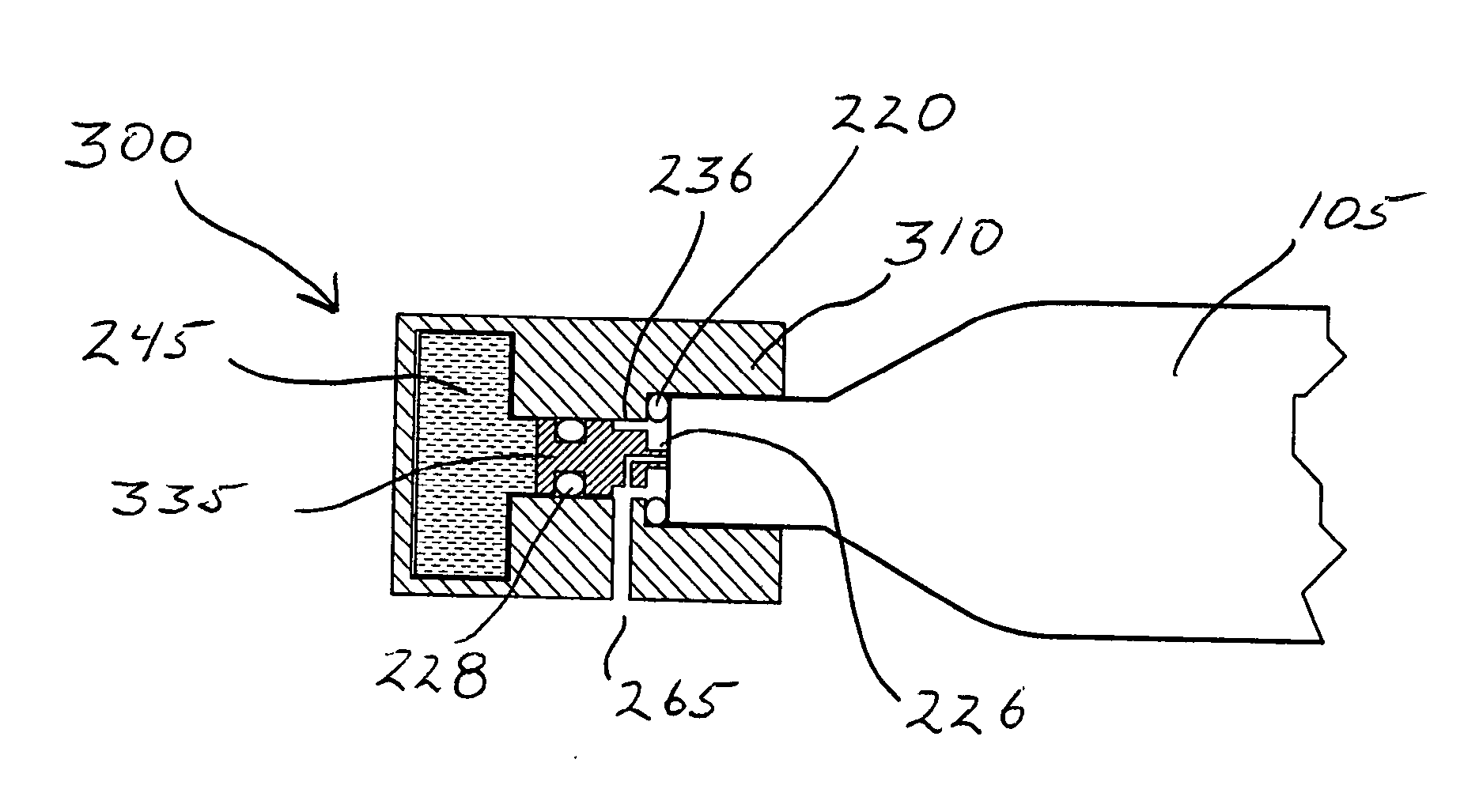
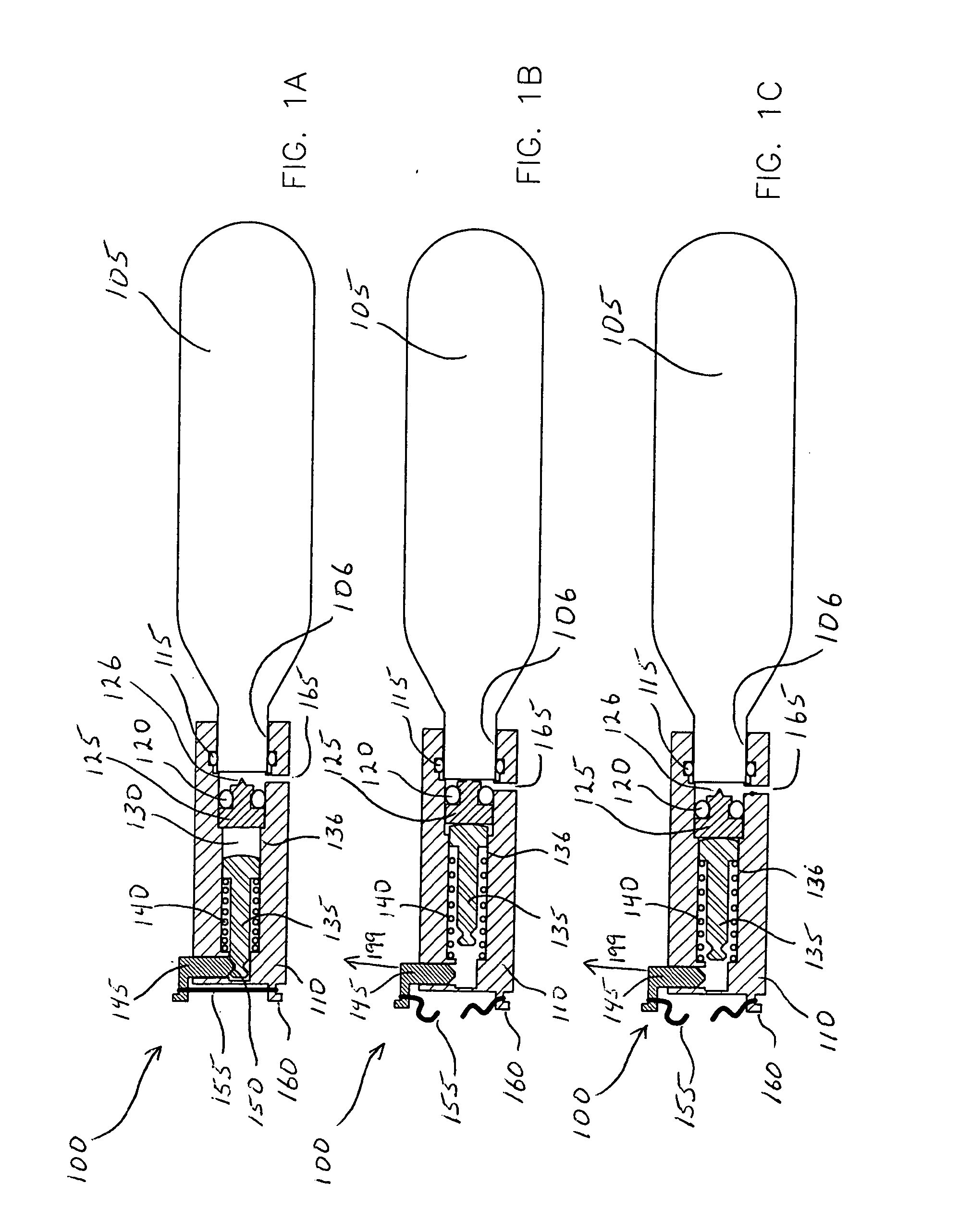
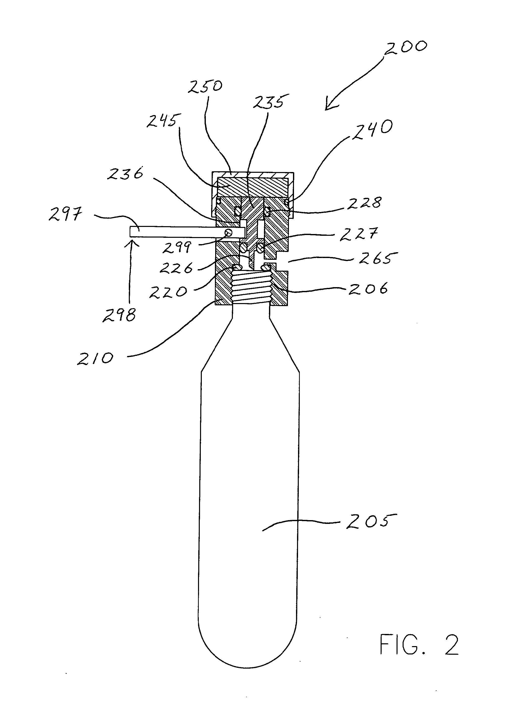
[0029]FIG. 1A illustrates a partial cross-section view of part of an exemplary compress gas cartridge (cgc) dispenser 100 in a first position comprising a non-threaded cgc functionally situated in a cgc dispenser, in accordance with the present invention. A cgc 105 situates within a lance housing 106 comprising a cgc seal 115 capable of retaining the pressure contained within a cgc upon h...


PUM


Abstract

The present invention offers a solution to the potential hazards associate with an accidental overbearing of a full compressed gas cartridge, by offering an automatic heat-actuable pressure discharge system.

Description

CROSS REFERENCE TO RELATED APPLICATIONS[0001]This Application is a Divisional Application claiming priority from a U.S. Utility Application having Ser. No. 11 / 344,322 filed Feb. 1, 2006.FEDERALLY SPONSORED RESEARCH[0002]Not applicable.REFERENCE TO A MICROFICHE APPENDIX[0003]Not applicable.FIELD OF INVENTION[0004]The present invention relates to the field of portable compressed gas cartridge dispensers comprising heat-actuable pressure relief systems.BACKGROUND OF THE INVENTION[0005]Hereinafter, a compressed gas cartridge will be referred as a cgc.[0006]Many people use compressed gas dispensers daily in a variety of applications such as medical, commercial and domestic. Common uses of such a dispenser are for use in the medical industry. Exemplary medical industry devices include: pneumatic inflation, cryogenic-related devices, pneumatic staple devices and dry powder and wet inhalers.[0007]Good hospital hygiene practices frequently include incineration of used disposable medical devi...

Claims


Application Information

Patent Timeline
Patent Type & Authority Applications(United States)
IPC IPC(8): F17C13/06F17C7/00
CPCF16K17/403F16K17/383B63C2009/0029F17C2201/058F17C2203/0617F17C2205/0317F17C2205/032F17C2223/0123F17C2223/036F17C2270/02F17C2270/0545F17C2270/0736F17C2270/0772Y10T137/1639Y10T137/1707Y10T137/1767Y10T137/1797
Inventor HOLLARS, ANTHONY SCOTTJANECEK, THOMAS F.
Owner HOLLARS ANTHONY S
Learn More