Toolbox structure of construction machine

a construction machine and toolbox technology, applied in soil-shifting machines/dredgers, manufacturing tools, transportation and packaging, etc., can solve the problems of rainwater or washing water collecting, discomfort of operators, and rainwater, washing water, etc., to flow into the box body

Active Publication Date: 2010-08-19
KOBELCO CONSTR MASCH CO LTD
View PDF14 Cites 25 Cited by
  • Summary
  • Abstract
  • Description
  • Claims
  • Application Information

AI Technical Summary

Benefits of technology

[0020]In this case, even if rainwater or the like flows into the box body through the illumination opening, the rainwater or the like can be drained to the outside of the box body through

Problems solved by technology

Therefore, there is a possibility that rainwater or washing water will collect in the recessed section.
If the water is in the recessed section when the operator opens the lid body, the hand of the operator will be wet, which causes discomfort to the operator.
In the case where an opening is provided in the bottom plate of the box body to increase the capacity of the toolbox, as in the toolbox structure described in

Method used


Image

  • Toolbox structure of construction machine
  • Toolbox structure of construction machine
  • Toolbox structure of construction machine

Examples


Embodiment Construction

[0028]An embodiment of the present invention will be described below with reference to the drawings. The preferred embodiment described below is basically an example, and is not intended to limit the present invention, the applications thereof, or the uses thereof.

Overall Structure of Construction Machine

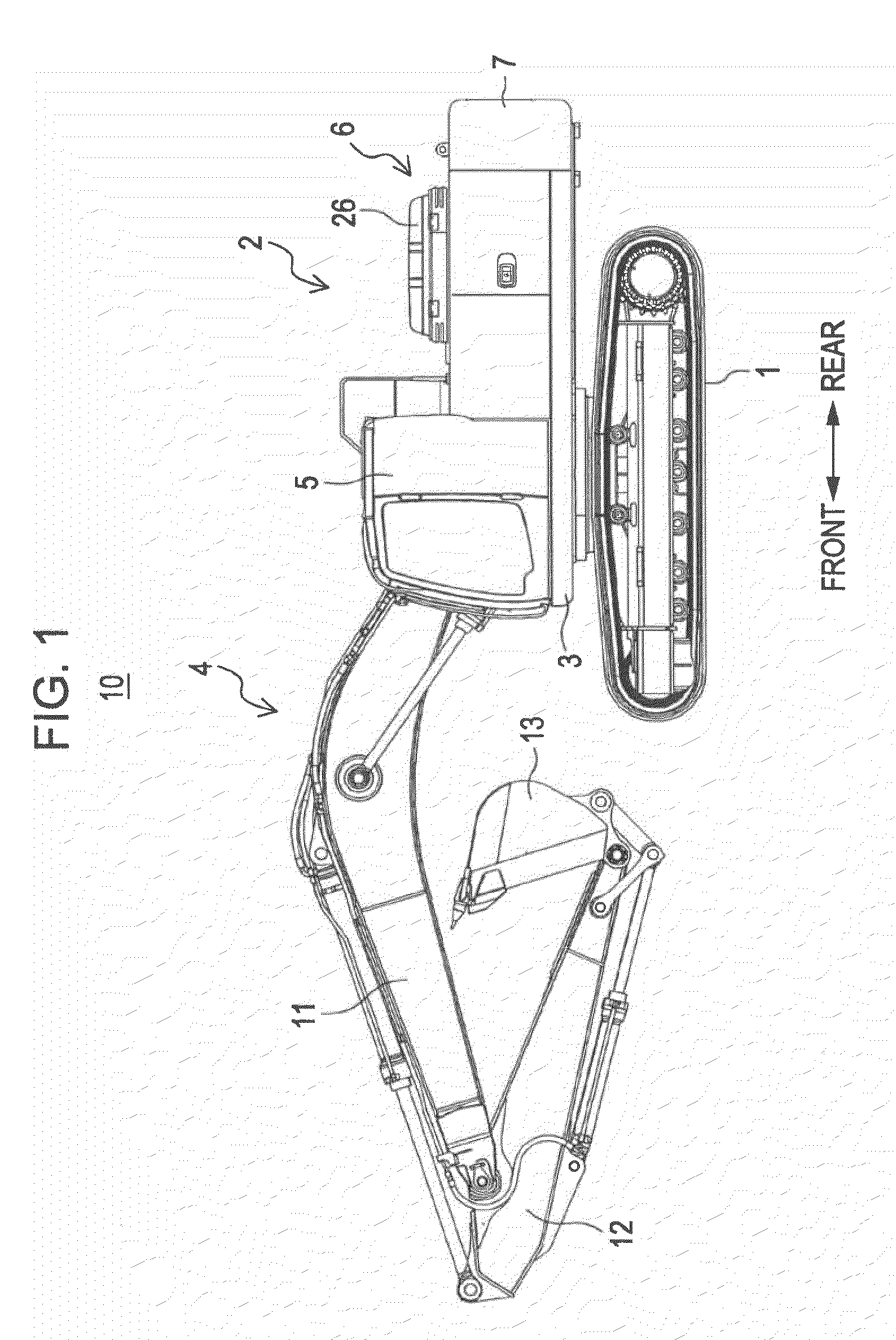
[0029]FIG. 1 is a side view illustrating the overall structure of a construction machine 10 to which the present invention is applied. As shown in FIG. 1, the construction machine 10 is a hydraulic excavator including a crawler-type lower travelling body 1 and an upper rotating body 2 (main frame) mounted on the lower travelling body 1 in a rotatable manner. The upper rotating body 2 includes a main frame 3 and an attachment 4, a cab 5, a machine room 6, a counterweight 7, etc., which are attached to the main frame 3.

[0030]In the present embodiment, referring to FIG. 1, the side at which the attachment 4 is disposed, that is, the left side in the figure, is called the front side of ...


PUM


Abstract

An illumination device is installed in a box body of a toolbox of a construction machine, and is protected by a protective cover. Water that flows into the box body through a weep hole formed in a lid is received by the protective cover and is guided to a water drain hole formed in a bottom plate of the box body. Then, the water is drained to the outside of the box body.

Description

BACKGROUND OF THE INVENTION[0001]1. Field of the Invention[0002]The present invention relates to a toolbox structure of a construction machine.[0003]2. Description of the Related Art[0004]A construction machine, such as a hydraulic excavator, includes a toolbox on a main frame so that various tools can be stored in the toolbox. For example, Japanese Unexamined Patent Application Publication No. 2001-262624 discloses a toolbox structure including a box body and a lid body. The box body has a storage space therein and is provided with an opening formed in an upper section of the box body. The lid body can open or close the opening in the box body. The lid body is provided with a handle that can be grabbed by an operator when the operator opens or closes the lid body. In this structure, a sealing member is provided between the box body and the lid body to prevent rainwater, washing water, etc., from flowing into the box body.[0005]In addition, Japanese Unexamined Patent Application Pub...

Claims


Application Information

Patent Timeline
IPC IPC(8): B60R11/06
CPCE02F9/00E02F9/0858E02F9/0891B60Q1/2661B60Q1/24B25H3/02E02F9/0833B60Q1/0005B60Q2800/20
Inventor NODA, TSUYOSHIKANAMARU, HIROSHI
Owner KOBELCO CONSTR MASCH CO LTD
Why Eureka
Try Eureka