
TDMA control method used by RFID reader via mobile phone base station and mobile RFID reader

a control method and mobile phone technology, applied in multiplex communication, wireless communication, instruments, etc., can solve problems such as inability to solve algorithms, interference or collision between readers, and disadvantages of conventional methods of reducing interference quantity by using fdm in limited number of available channels, so as to avoid interference between readers

Inactive Publication Date: 2010-08-19
ELECTRONICS & TELECOMM RES INST
View PDF4 Cites 24 Cited by
  • Summary
  • Abstract
  • Description
  • Claims
  • Application Information

AI Technical Summary

Benefits of technology

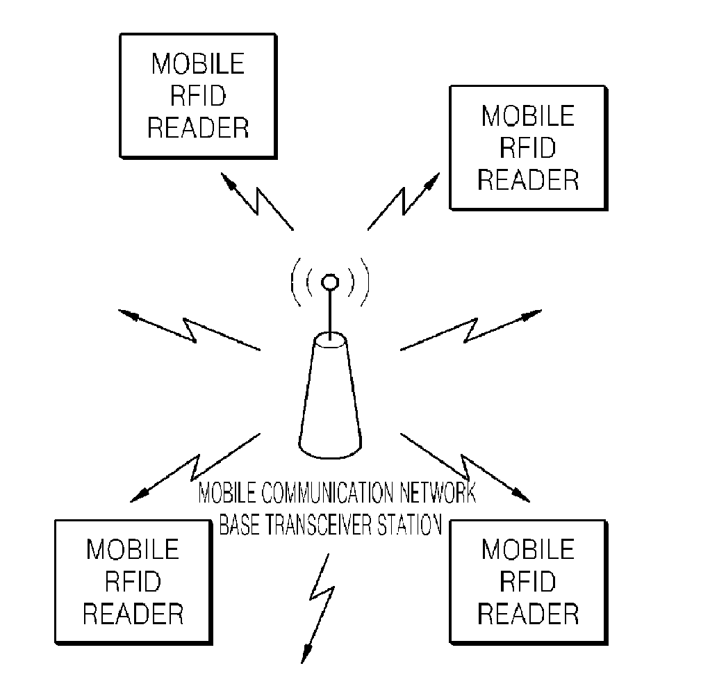
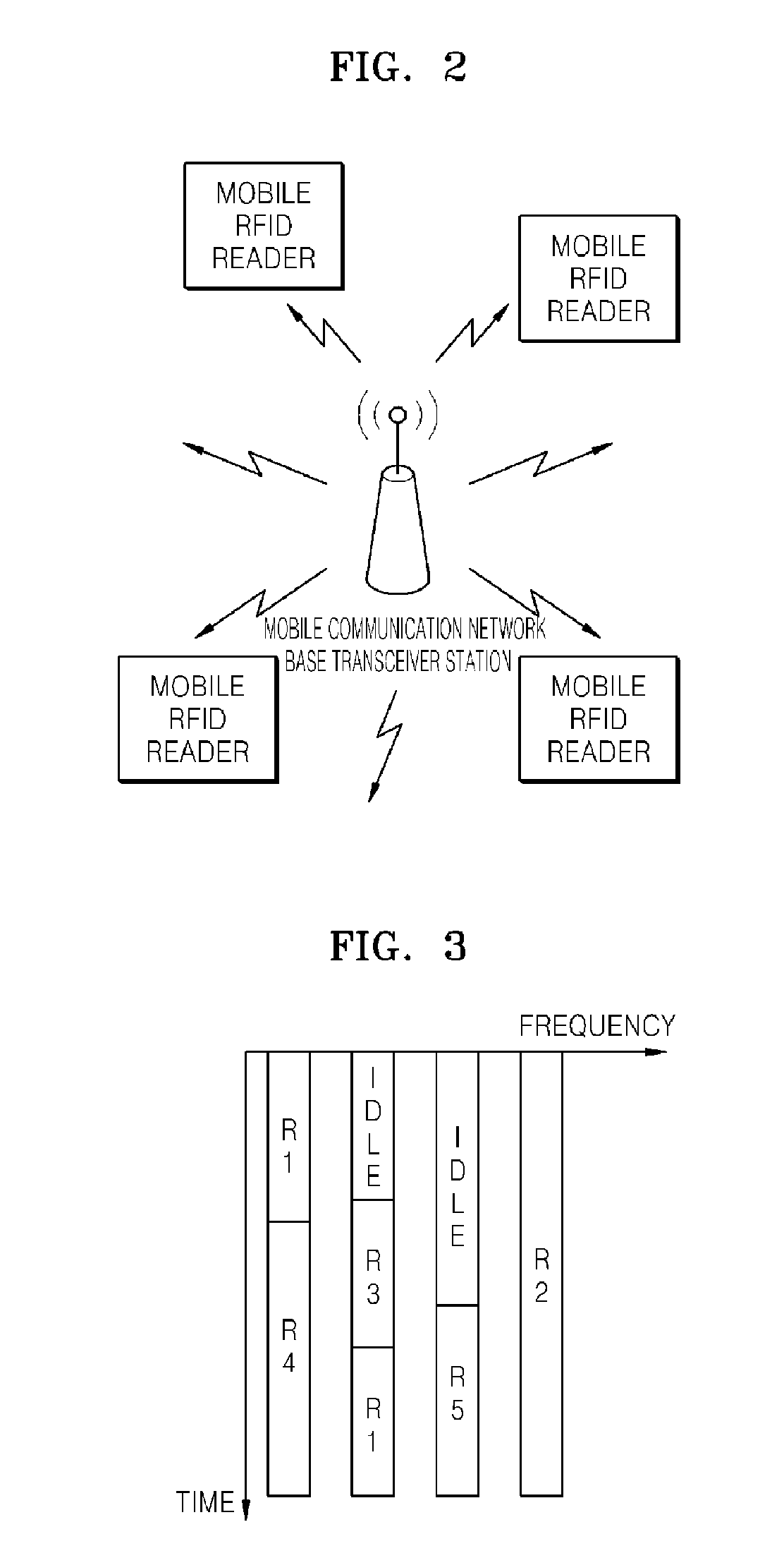
[0010]The present invention allocates frequency channels and RFID communication channels regarding time slots over a mobile communication base station to a mobile RFID reader, thereby controlling mobile RFID readers by using TDM.
[0011]Therefore, each mobile RFID reader occupies an allocated frequency and time slot, thereby avoiding interference between readers.
[0012]Also, a base station and mobile RFID readers use a given channel of a corresponding network to communicate RFID communication channel information, which extends a given network protocol, thereby allocating channels for an RFID communication without establishing an additional control channel.

Problems solved by technology

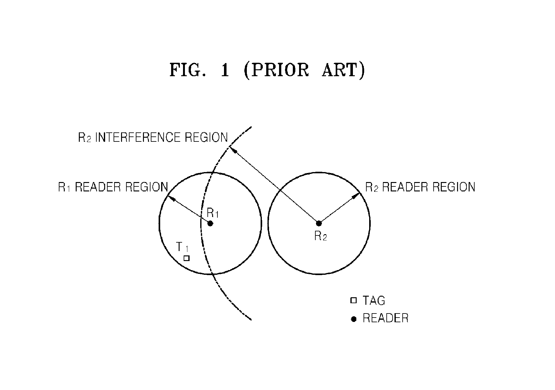
Referring to FIG. 1, the interference or collision between readers has been a critical problem in a multiple reader environment where a plurality of readers is used in a specific region.
However, such algorithms have failed to solve a problem, such as a hidden terminal.
However, the conventional method of reducing the interference quantity by using the FDM has a disadvantage in the limited number of available channels.
Although time division multiplexing (TDM) is used to temporally divide a channel that can be shared by a plurality of readers, it is difficult to implement the TDM in an environment where there is no central device for allocating timeslots to different end equipments.
However, since a mobile RFID reader has not central network management node, it is difficult to implement the mobile RFID reader and thus the TDM has not been widely used for a mobile RFID field up to now.

Method used


Image

  • TDMA control method used by RFID reader via mobile phone base station and mobile RFID reader
  • TDMA control method used by RFID reader via mobile phone base station and mobile RFID reader
  • TDMA control method used by RFID reader via mobile phone base station and mobile RFID reader

Examples


Embodiment Construction

[0029]The present invention will now be described more fully with reference to the accompanying drawings, in which exemplary embodiments of the invention are shown. Although like elements are shown in different figures, like reference numerals in the drawings denote like elements. While describing the present invention, detailed descriptions about related well known functions or configurations that may blur the points of the present invention are omitted.

[0030]Unless explicitly described to the contrary, the word ‘comprise’ and variations such as ‘comprises’ or ‘comprising’, will be understood to imply the inclusion of stated elements but not the exclusion of any other elements. The term ‘unit’ in the embodiments of the present invention means a software component or hardware components or a combination thereof, and performs a specific function or operation.

[0031]FIG. 2 is a schematic diagram of a mobile radio frequency identifier (RFID) system according to an embodiment of the pres...


PUM


Abstract

A time division multiple access (TDMA) control method used by a mobile radio frequency identifier (RFID) reader through a mobile phone base station and a mobile RFID reader are provided. Each mobile RFID reader occupies a frequency channel during a time slot allocated through a mobile communication base station, thereby avoiding interference between readers.

Description

TECHNICAL FIELD [0001]The present invention relates to a mobile radio frequency identifier (RFID) reader control method, and more particularly to, a time division multiplexing (TDM) control method applicable to a mobile RFID reader via a mobile phone base station.[0002]The present invention is supported by the Information Technology (IT) Research & Development (R&D) program of the Ministry of Information and Communication (MIC) and the Institute for Information Technology Advancement (IITA) [2006-S-023-02, Development of Advanced RFID System Technology].[0003]This application claims the benefit of Korean Patent Application Nos. 10-2007-0103149, filed on Oct. 12, 2007, 10-2008-0078119, filed on Aug. 8, 2008, in the Korean Intellectual Property Office, the disclosure of which is incorporated herein in its entirety by reference.BACKGROUND ART [0004]FIG. 1 is a conceptual diagram of interference between readers. Referring to FIG. 1, the interference or collision between readers has been...

Claims


Application Information

Patent Timeline
IPC IPC(8): G06K17/00
CPCG06K7/0008G06K7/10475H04W72/0413H04W74/0833H04W72/0446H04W72/082H04W74/006H04W72/042H04W72/21H04W72/541H04W72/23H04W72/04H04J3/00H04B5/00
Inventor PARK, CHAN-WONSEONG, NAK-SEONPREISHUBER-PFLUEGL, JOSEFTSCHISCHE, DAVIDCHOI, GIL-YOUNGPYO, CHEOL-SIGCHAE, JONG-SUK
Owner ELECTRONICS & TELECOMM RES INST
Learn More