Radio Base Station and Transmission Control Method

a radio signal and control method technology, applied in the direction of wireless communication, power management, sustainable buildings, etc., can solve the problem that the radio base station cannot increase the transmission power of the radio signal to be transmitted to the radio communication terminal, and achieve the effect of increasing the transmission power of the radio signal and low reception quality

Inactive Publication Date: 2010-08-19
KYOCERA CORP
View PDF4 Cites 2 Cited by
  • Summary
  • Abstract
  • Description
  • Claims
  • Application Information

AI Technical Summary

Benefits of technology

[0007]Specifically, when the radio communication terminal is located near the radio base station, the propagation path quality between the radio communication terminal and the radio base station is high. Accordingly, the transmission power from the radio base station to the radio communication terminal is increased more than necessary though the communication is executed at the low data rate.
[0025]According to the first to fifth aspects of the present invention, it is possible to provide the radio base station and the transmission control method which are capable of increasing the transmission power of the radio signal to be transmitted to the radio communication terminal having low reception quality even when the amplifier in the transmitter of the radio base station is close to saturation. Meanwhile, according to the sixth to eleventh aspects of the present invention, it is possible to control the transmission power for the multiple radio communication terminals properly even when the amplifier in the transmitter of the radio base station is close to saturation.

Problems solved by technology

However, when the radio base station transmits radio signals to multiple radio communication terminals at the same time, there may be a case where an amplifier in a transmitter of the radio base station is close to saturation.
In this case, even if the radio base station receives a request for increasing the transmission power from a radio communication terminal, the radio base station cannot increase the transmission power of the radio signal to be transmitted to the radio communication terminal.
Meanwhile, under a situation where the amplifier in the transmitter of the radio base station is close to saturation, the following problem occurs when communication at a low data rate (data quantity) is executed between the radio base station and a certain radio communication terminal, or when a downlink CNR in the radio communication terminal is higher than a CNR required for a modulation class applied to a radio signal to be transmitted to the radio communication terminal.

Method used


Image

  • Radio Base Station and Transmission Control Method
  • Radio Base Station and Transmission Control Method
  • Radio Base Station and Transmission Control Method

Examples


first embodiment

[0050]Next, a first embodiment of the present invention will be described with reference to the drawings. In the following description of the drawings of the first embodiment, identical or similar constituents are designated by identical or similar reference numerals.

[0051]The first embodiment will be described in the order of (1) an overall schematic configuration, (2) a configuration of the radio base station, (3) transmission power control processing, go (4) an interference countermeasure, (5) an operation of the radio base station, and (6) effects and advantages.

[0052](1) Overall Schematic Configuration

[0053]Firstly, an overall schematic configuration of a radio communication system according to the first embodiment will be described.

[0054](1.1) Configuration of Radio Communication System

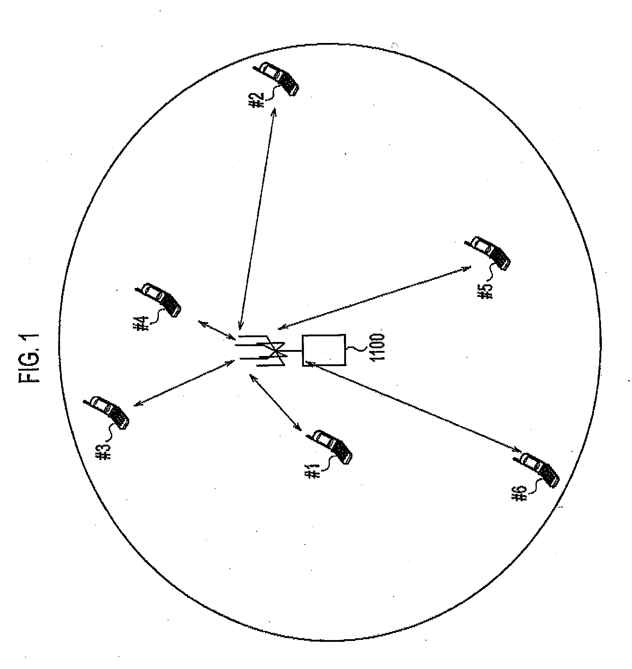
[0055]FIG. 1 is an overall schematic configuration diagram of the radio communication system according to the first embodiment. As shown in FIG. 1, the radio communication system according to th...

second embodiment

[0142]Next, a second embodiment of the present invention will be described with reference to the drawings. In the following description of the drawings of the second embodiment, identical or similar constituents are designated by identical or similar is reference numerals.

[0143]The second embodiment will be described in the order of (1) an overall schematic configuration, (2) a configuration of the radio base station, (3) transmission power control processing, (4) an interference countermeasure, (5) an operation of the radio base station, and (6) effects and advantages.

[0144](1) Overall Schematic Configuration

[0145]Firstly, an overall schematic configuration of a radio communication system according to the second embodiment will be described.

[0146](1.1) Configuration of Radio Communication System

[0147]FIG. 13 is an overall schematic configuration diagram of the radio communication system according to the second embodiment. As shown in FIG. 13, the radio communication system accordin...


PUM


Abstract

A transmission control method according to the present invention includes: step S1104 of judging whether a sum of transmission power at timing of transmitting radio signals to the plurality of radio communication terminals reaches a threshold; step S1106 of judging whether it is possible to reduce the transmission power of a radio signal to be transmitted to a second radio communication terminal when the sum is judged to reach the threshold; and step S1108 of reducing the transmission power of the radio signal to be transmitted to the second radio communication terminal and increasing the transmission power of a radio signal to be transmitted to a first radio communication terminal, when it is judged that it is possible to reduce the transmission power of the radio signal to be transmitted to the second radio communication terminal.

Description

TECHNICAL FIELD[0001]The present invention relates to a radio base station and a transmission control method for transmitting radio signals simultaneously to multiple radio communication terminals including a first radio communication terminal and a second radio communication terminal.BACKGROUND ART[0002]Adaptive modulation has heretofore been known as a technique to enhance a communication rate in a radio communication system. In a radio communication system using the adaptive modulation, a radio base station communicates with a radio communication terminal by using a modulation class having a high communication rate when quality of a radio propagation path with the radio communication terminal (hereinafter “propagation path quality”) is high.[0003]The orthogonal frequency division multiplexing access (OFDMA) is known as a communication method that uses numerous subcarriers. In a radio communication system using the OFDMA, a different modulation class can be applied to each subcarr...

Claims


Application Information

Patent Timeline
IPC IPC(8): H04B7/005H04W52/06H04W52/14H04W52/24H04W52/34
CPCH04L1/0003H04W52/143H04W52/241Y02B60/50H04W52/247H04W52/346H04W52/243
Inventor KAWAJI, SATOSHI
Owner KYOCERA CORP
Why Eureka
Try Eureka