Thermoacoustic driven compressor

a compressor and motor technology, applied in the field of thermoacoustic engines, can solve the problems of inapplicability to the configuration, inability to operate, and oscillation of gas displacemen

Inactive Publication Date: 2010-08-26
ENOVA
View PDF32 Cites 67 Cited by
  • Summary
  • Abstract
  • Description
  • Claims
  • Application Information

AI Technical Summary

Benefits of technology

[0038]It is to be understood that both the foregoing general description and the following detailed description are exemplary and explanatory only, and are not restrictive of the invention, as claimed. In this application, the use of the singular includes the plural, the word “a” or “an” may mean a singular object or element, or it may mean a plurality, at least one, or one or more of such objects or elements, and the use of “or” means “and/or”, unless specifically stated otherwise. Throughout this disclosure, unless the context dictates otherwise, the word “comprise” or variations such as “comprises” or “comprising,” is understood to mean “includes, but is not limited to” such that other elements that are not explicitly mentioned may also be included. Furthermore, the use of the term “including”, as well as other forms, such as “inclu

Problems solved by technology

The standing wave time phasing characteristics are due to very poor thermal contact between the gas and the stack (e.g., because of large pore size), which allows gas pressure and relative gas displacement oscillations to be in phase with the gas thermal expansion and contraction.
However, in this case the pores are

Method used


Image

  • Thermoacoustic driven compressor
  • Thermoacoustic driven compressor
  • Thermoacoustic driven compressor

Examples


Embodiment Construction

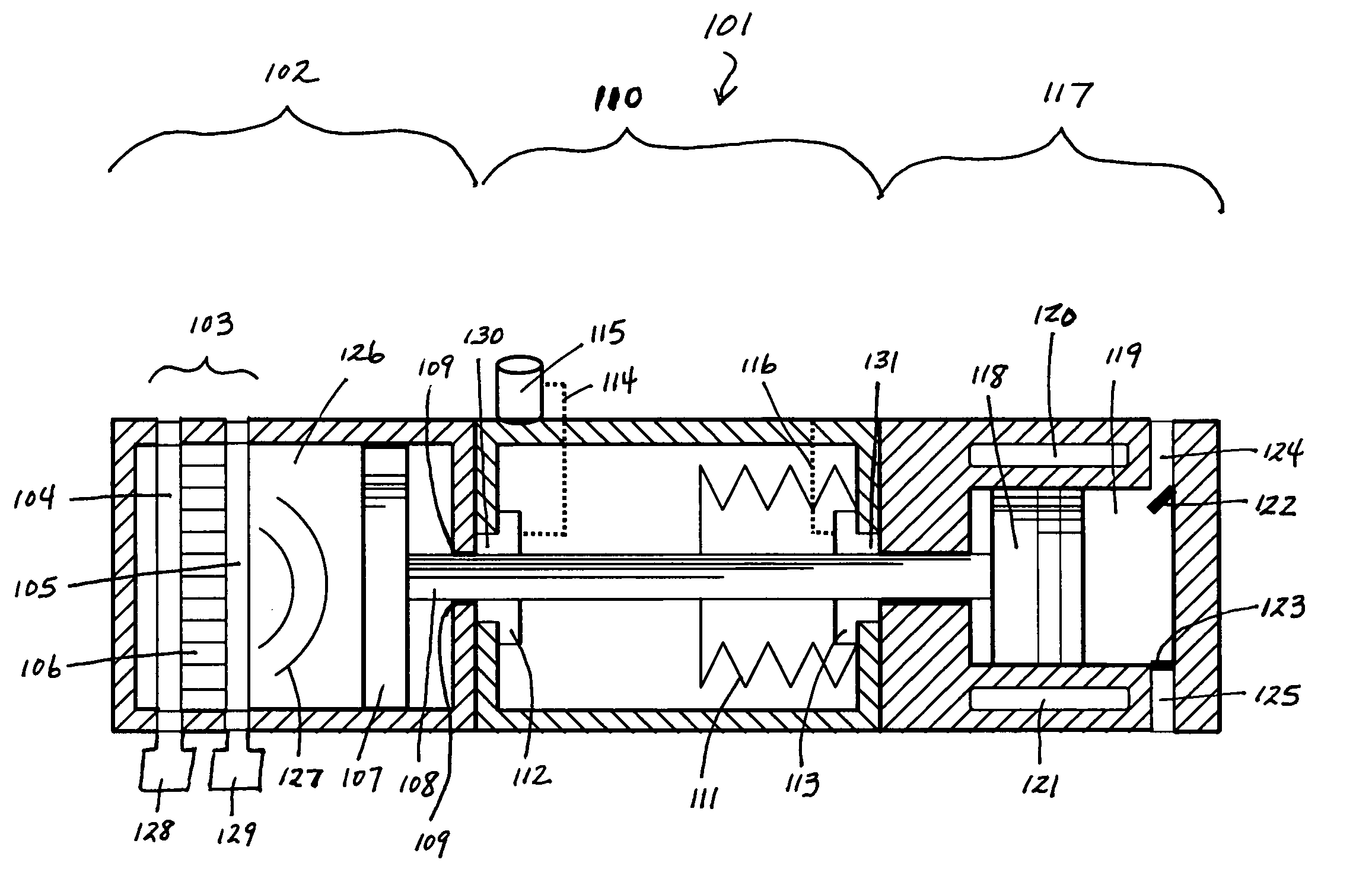
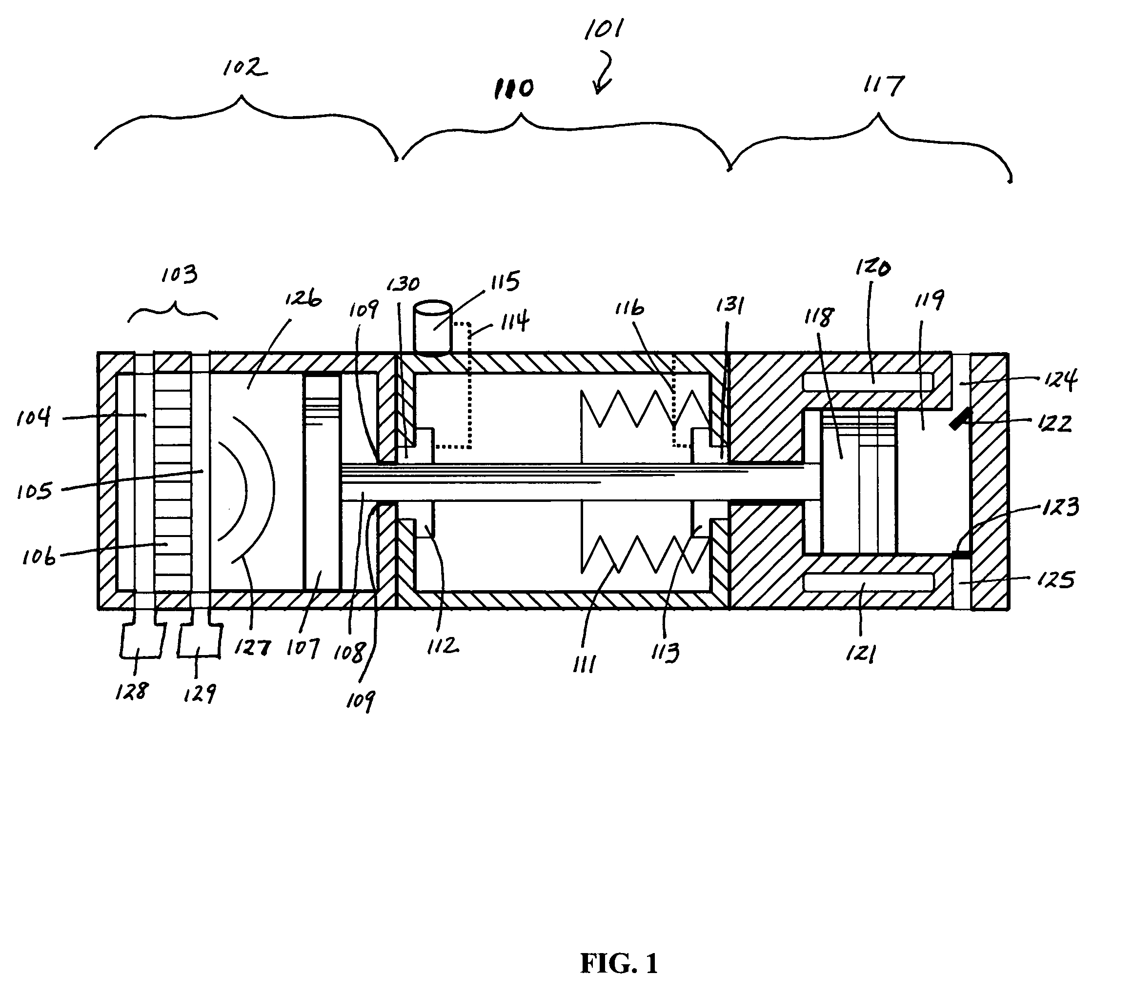
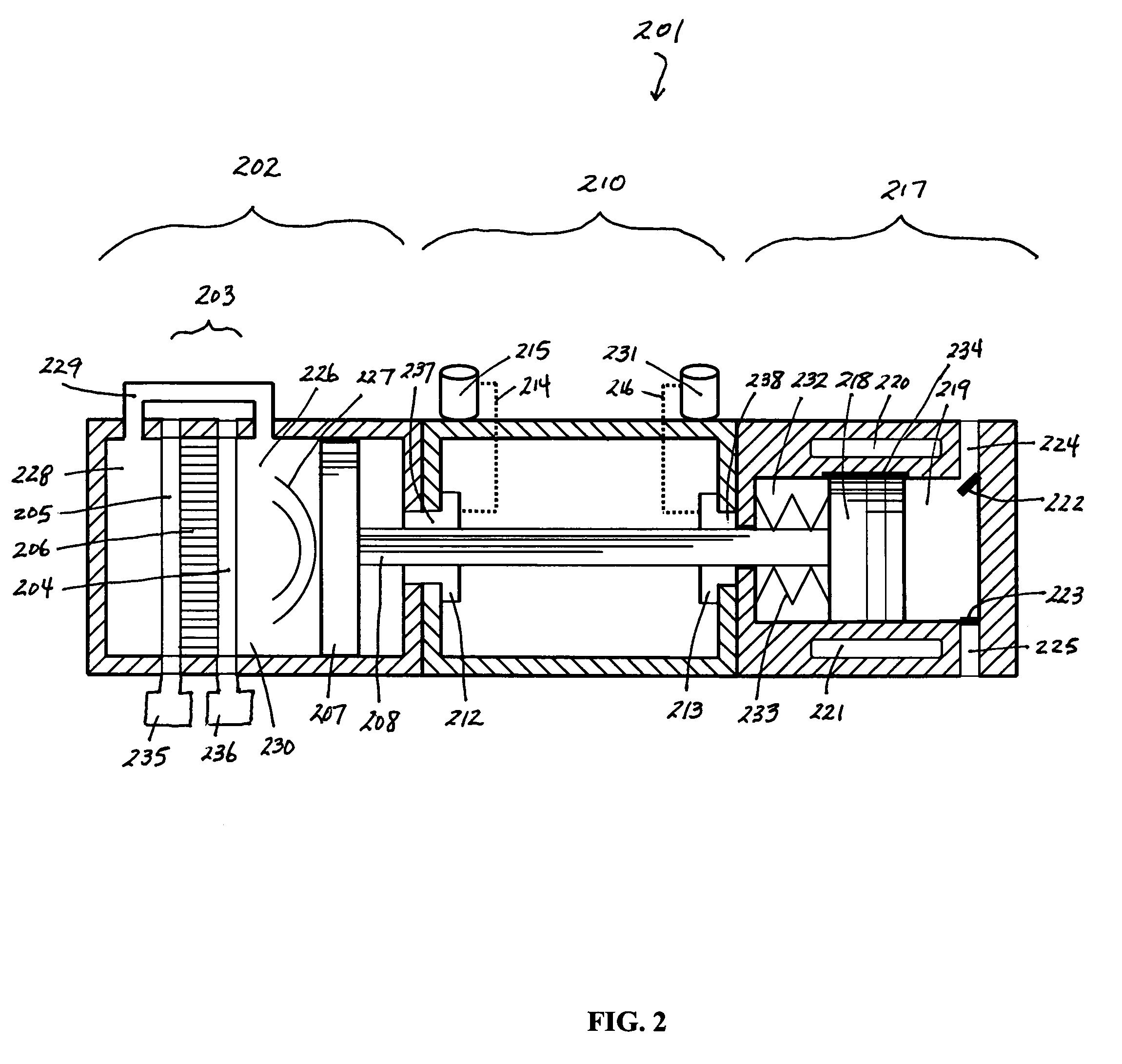
[0053]The present disclosure provides for a thermoacoustic driven compressor (“TADC”) that can utilize a heat driven standing or traveling wave thermoacoustic engine of any variation (e.g., requiring the use of a stack, regenerator, torus, hybrid (e.g., cascade), bellows, or any variation thereof), to power any type of reciprocating compressor or pump. A general discussion follows of exemplary TADCs containing three housings. These housings (thermoacoustic, distance, and compression) can have multiple mating surfaces and means of connecting mating surfaces to each other and / or to other structures. These housings can also be different sizes, vary in shape, and be separate from each other. It will be understood that the following discussion is not meant to be limiting, and that a TADC with greater or fewer housings or multiple components (from thermoacoustic, distance, compression, etc.) combined under one housing are within the scope of the present invention. It will also be understo...


PUM


Abstract

The present disclosure details a thermoacoustic driven compressor having a pressurized housing, which contains within a thermoacoustic engine and a working gas, coupled to a positive displacement reciprocating compressor. The thermoacoustic driven compressor generates scalable compressed air from a given heat source.

Description

CROSS-REFERENCE TO RELATED APPLICATIONS[0001]N / ASTATEMENT REGARDING FEDERALLY SPONSORED RESEARCH OR DEVELOPMENT[0002]N / ATHE NAMES OF PARTIES TO A JOINT RESEARCH AGREEMENT[0003]N / AINCORPORATION-BY-REFERENCE OF MATERIAL SUBMITTED ON A COMPACT DISC[0004]N / ABACKGROUND OF THE INVENTION[0005]1. Field of the Invention[0006]The present disclosure relates to systems and methods for utilizing a thermoacoustic engine with a positive displacement reciprocating compressor.[0007]2. Background of the Invention[0008]Due to the increasing costs and environmental concerns associated with hydrocarbon-based energy, society has recently shown greater interest in technologies that promote energy efficiency and alternative sources of energy. One technology that shows great promise in both fields is a thermoacoustic prime mover, which converts heat from any source to acoustic energy (i.e., an acoustic pressure wave).[0009]In general, a thermoacoustic engine consists of a hermetically sealed cylinder housin...

Claims


Application Information

Patent Timeline
IPC IPC(8): F02G1/04
CPCF25B9/14F25B2309/1404F25B2309/1403
Inventor MCQUARY, BRYAN O.COLE, STEVE M.
Owner ENOVA
Why Eureka
Try Eureka