High frequency thermoacoustic refrigerator

a high-frequency, refrigerator technology, applied in refrigeration machines, gas cycle refrigeration machines, lighting and heating apparatus, etc., can solve the problems of not being practical for small-scale applications, generating significant heat, electromagnetic drivers, etc., to achieve maximum efficiency, maximize temperature difference, and the effect of greatest cooling

Inactive Publication Date: 2007-07-10
UNIV OF UTAH RES FOUND
View PDF38 Cites 24 Cited by
  • Summary
  • Abstract
  • Description
  • Claims
  • Application Information

AI Technical Summary

Benefits of technology

[0017]Utilizing a driver that operates at a high frequency allows the thermoacoustic device of the present invention to be made smaller in size as the wavelength at such a frequency is short. Thus, the present invention provides a compact thermoacoustic refrigerator in which its dimensions scale with the wavelength of the audio drive.
[0046]Since the optimum position of the stack within the chamber resulting in the optimal temperature difference across the stack is a function of the length of the stack in association with the frequency and the wavelength of the sound wave, it may be desirable to allow adjustment of the length of the resonator or adjustment of the position of the stack / heat exchanger unit at the optimal position in the resonator to “tune” the resonator or stack / heat exchanger, as the case may be, for maximum efficiency. Thus, the method of cooling further includes adjusting the position of the stack and heat exchangers within the resonator to maximize the temperature difference between the first and second heat exchangers for a given driver.

Problems solved by technology

For an electromagnetic driver, power density scales as x making it not as practical for small scale applications.
An electromagnetic driver, on the other hand, has a typical voice coil resistance of 8 ohms and produces significant heat.

Method used


Image

  • High frequency thermoacoustic refrigerator
  • High frequency thermoacoustic refrigerator
  • High frequency thermoacoustic refrigerator

Examples


Embodiment Construction

[0061]Reference is now made to the drawings wherein like parts are designated with like numerals throughout. It should be noted that the present invention is discussed in terms of a thermoacoustic refrigerator operating at a frequency of approximately 4,000 Hz or more. After understanding the present invention, however, those skilled in the art will appreciate that the frequency and size of components used therewith can be readily miniaturized in accordance with the teachings provided herein.

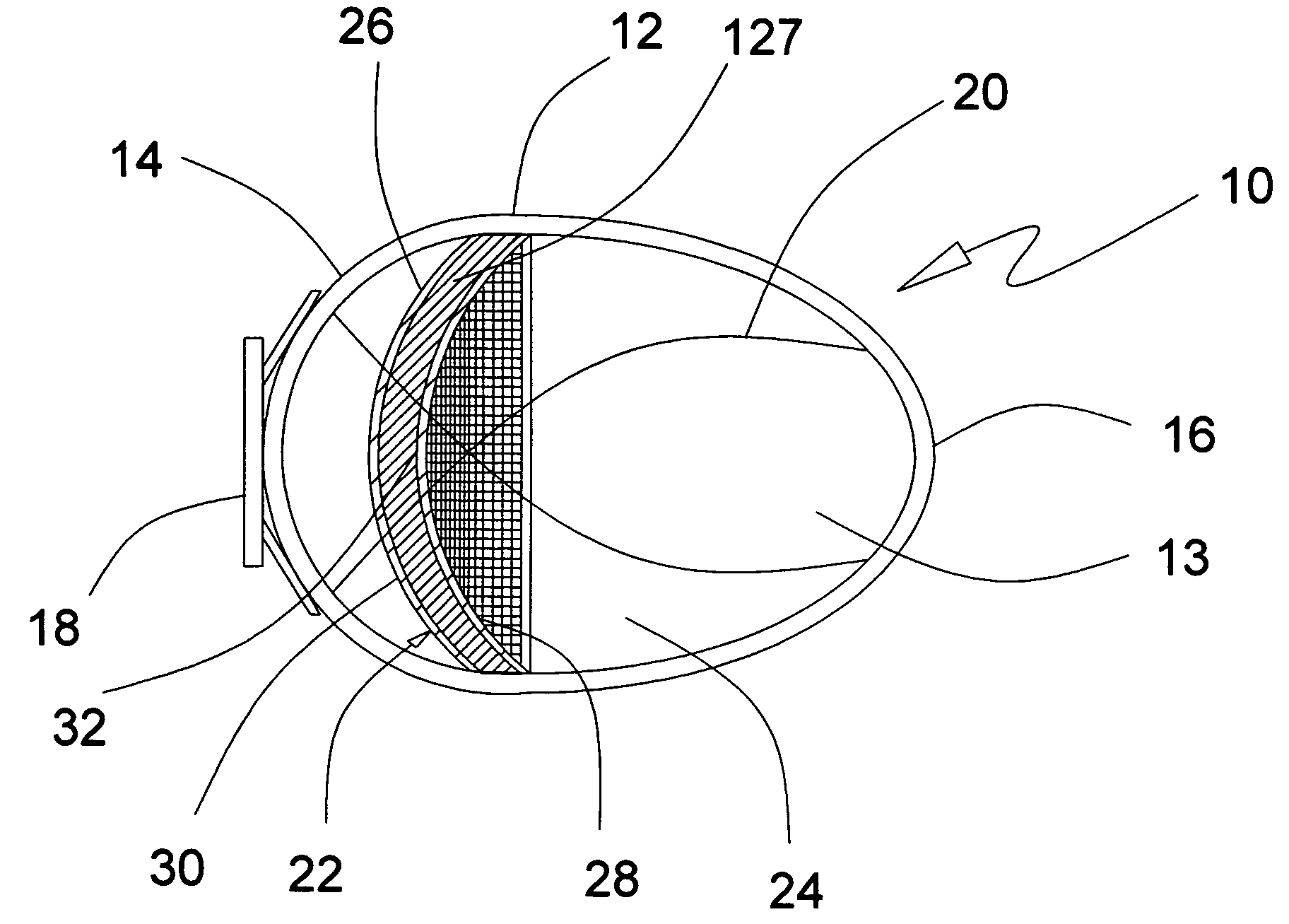
[0062]Referring now to FIG. 1, a compact thermoacoustic refrigerator, generally indicated at 10, is illustrated. The thermoacoustic refrigerator 10 is comprised of a resonator 12 forming an enclosure for housing some of the components of the thermoacoustic refrigerator 10. The resonator 12 is an enclosed structure having an elliptical, ovoid or “egg” shape defining an interior chamber 13 of a similar asymmetrical shape when viewed in cross-section along a longitudinal length of the resonator 12 ...


PUM


Abstract

A thermoacoustic refrigerator having a relatively small size which utilizes one or more piezoelectric drivers to generate high frequency sound within a resonator at a frequency of between about 4000 Hz and ultrasonic frequencies. The interaction of the high frequency sound with one or more stacks create a temperature gradient across the stack which is conducted through a pair of heat exchangers located on opposite sides of each stack. The resonator has an asymmetrical, round configuration which enhances the cooling power of the thermoacoustic refrigerator.

Description

CROSS-REFERENCE TO RELATED APPLICATIONS[0001]The present application is a continuation-in-part of U.S. patent application Ser. No. 10 / 458,752 filed on Jun. 10, 2003, now U.S. Pat. No. 6,804,967, which is a continuation of U.S. patent application Ser. No. 09 / 898,539 filed on Jul. 2, 2001, now U.S. Pat. No. 6,574,968, herein incorporated by this reference.FUNDING[0002]The present application has been at least partially funded by the Office of Naval Research contract numbers PE 61153 N and N00014-93-1-1126.BACKGROUND[0003]1. Field of the Invention[0004]The present invention relates generally to thermoacoustic refrigerators and, more specifically, to a thermoacoustic refrigerator having a relatively small size which utilizes one or more piezoelectric drivers to generate high frequency sound within a resonator. The interaction of the high frequency sound with one or more stacks create a temperature difference across the stack which is thermally anchored at each end to a pair of heat exch...

Claims


Application Information

Patent Timeline
Patent Type & Authority Patents(United States)
IPC IPC(8): F25B9/00F25B9/14
CPCF25B9/145F02G2243/54F25B2309/1402
Inventor SYMKO, OREST G.ABDEL-RAHMAN, EHAB
Owner UNIV OF UTAH RES FOUND
Why Eureka
Try Eureka