
Assembled configuration of cooling fins and heat pipes

a technology of cooling fins and heat pipes, which is applied in the direction of indirect heat exchangers, lighting and heating apparatus, tubular elements, etc., can solve the problems of uneven distribution or leakage of thermal interface materials, and achieve enhanced stability of cooling fins, facilitate filling of thermal interface materials, and facilitate the effect of cooling fins

Inactive Publication Date: 2010-08-26
SUPER MICRO COMP +1
View PDF71 Cites 1 Cited by
  • Summary
  • Abstract
  • Description
  • Claims
  • Application Information

AI Technical Summary

Benefits of technology

[0007]Therefore, in view of the drawbacks of prior art, the present inventor developed an assembled configuration of cooling fins and heat pipes as disclosed herein which facilitates filling of the thermal interface material between the cooling fins and the heat pipes and enhances stability of the cooling fins.
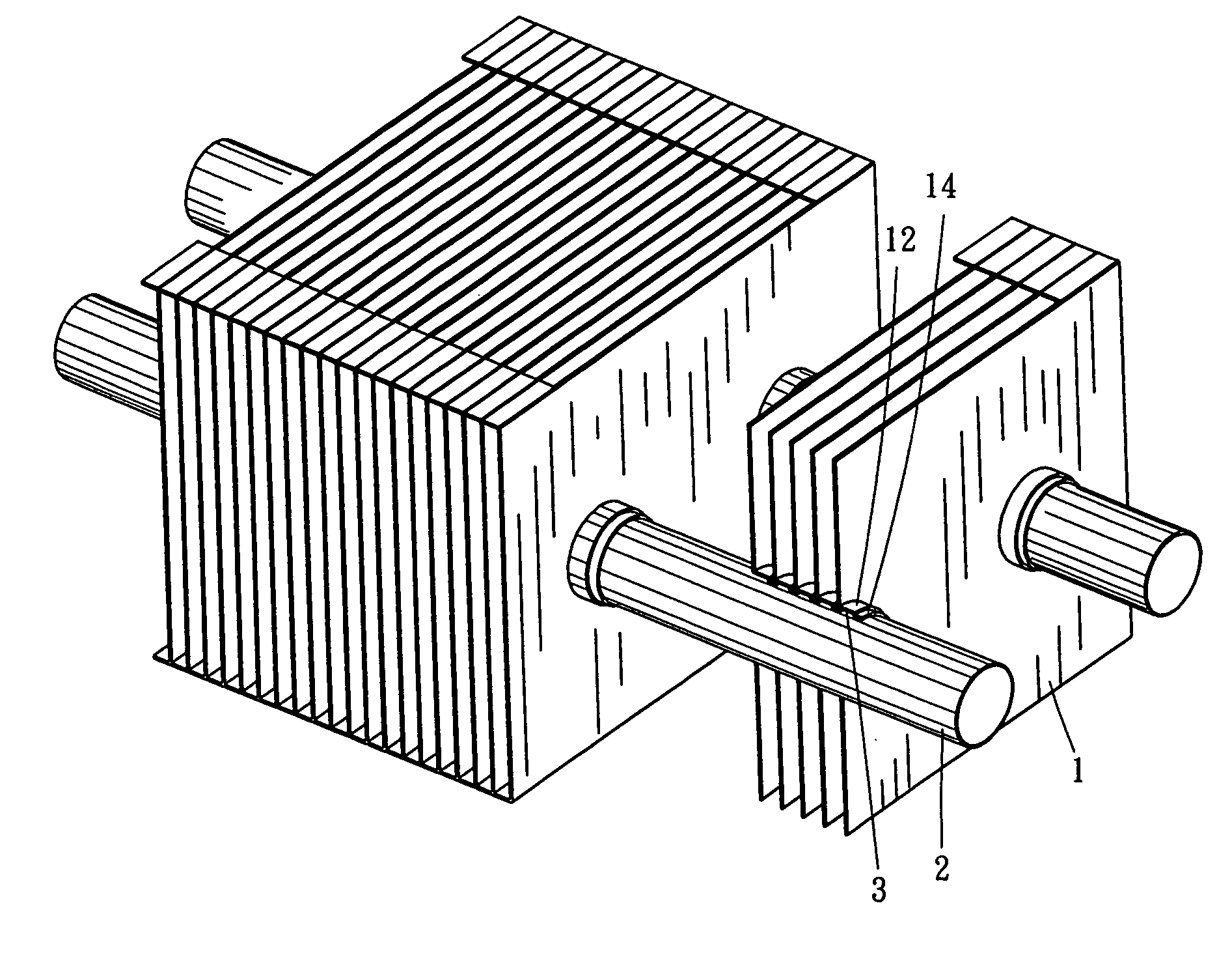
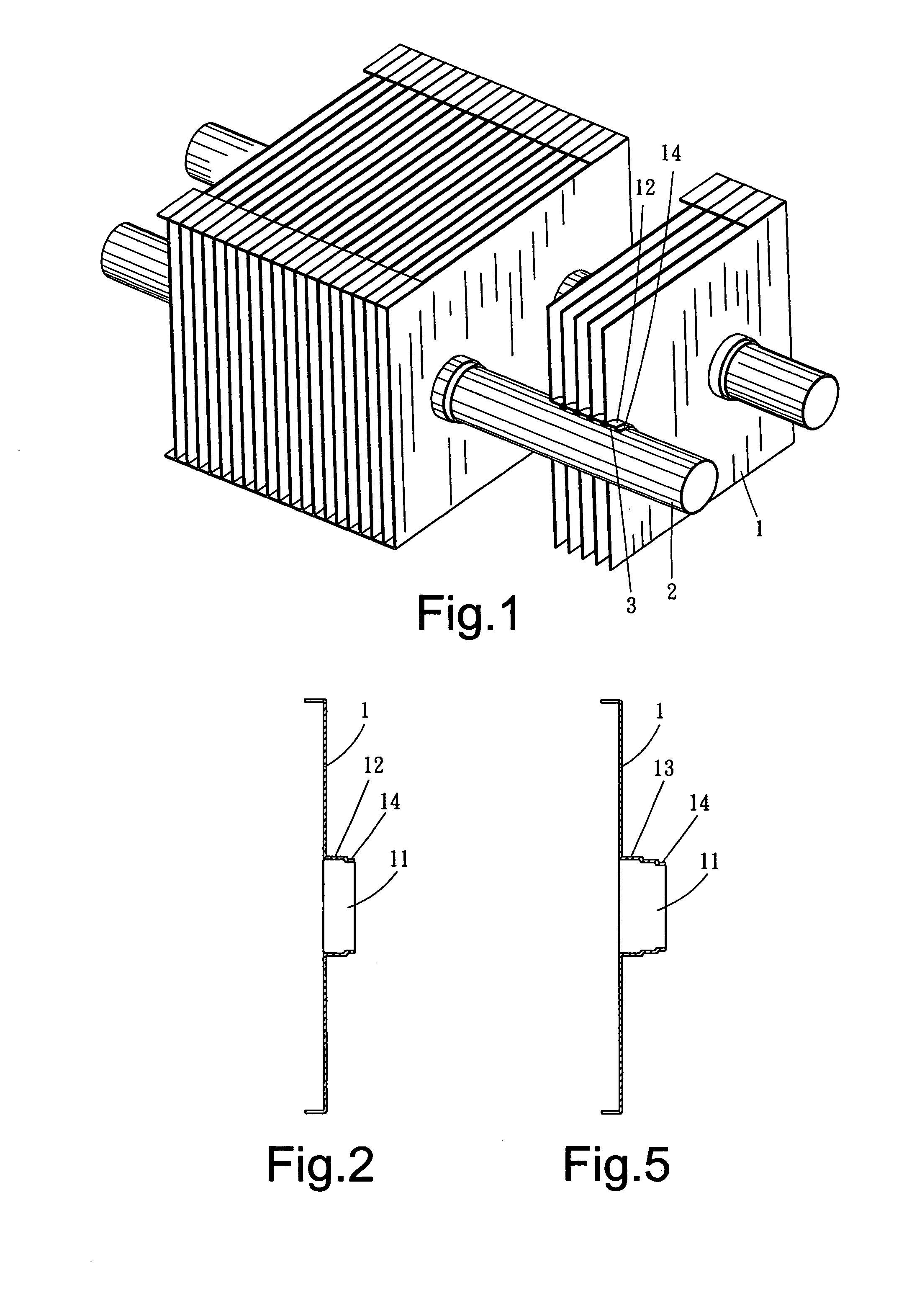
[0008]The assembled configuration of cooling fins and heat pipes according to the present invention is characterized in that each of the cooling fins is formed at an end thereof contacting the heat pipes with a bent portion having at least two bent sections so as to define an accommodating space for a thermal interface material and an extending section to be nestingly overlapped, wherein the accommodating space can be sufficiently filled with the thermal interface material and the extending section allows an adjacent said cooling fin to be nestingly placed thereon so that not only a closed accommodating space for the thermal interface material is formed between each two adjacent said cooling fins, but also gaps between each said cooling fin and the heat pipes are completely sealed, effectively preventing the thermal interface material from leaking out. Moreover, by overlapping one cooling fin on top of another, stability of the cooling fins is also enhanced.

Problems solved by technology

However, the aforementioned conventional approach of applying or filling the thermal interface material between the heat pipes and the cooling fins, as described in Taiwan Patent Publication Nos. 518927, 547002 and M283152, tends to incur such problems as uneven distribution or leakage of the thermal interface material or contamination by the thermal interface material.

Method used


Image

  • Assembled configuration of cooling fins and heat pipes
  • Assembled configuration of cooling fins and heat pipes
  • Assembled configuration of cooling fins and heat pipes

Examples


Embodiment Construction

[0015]As shown in FIGS. 1 and 2, an assembled configuration of cooling fins and heat pipes according to the present invention is characterized in that each of the cooling fins 1 has through holes 11 for heat pipes 2 to pass through, and each said through hole 11 is formed with a stair-shaped bent portion 12 at a periphery thereof having an extending section 14 formed at an distal end of said stair-shaped bent portion 12, wherein the extending section 14 has an outer diameter approximately equal to an inner diameter of the stair-shaped bent portion 12.

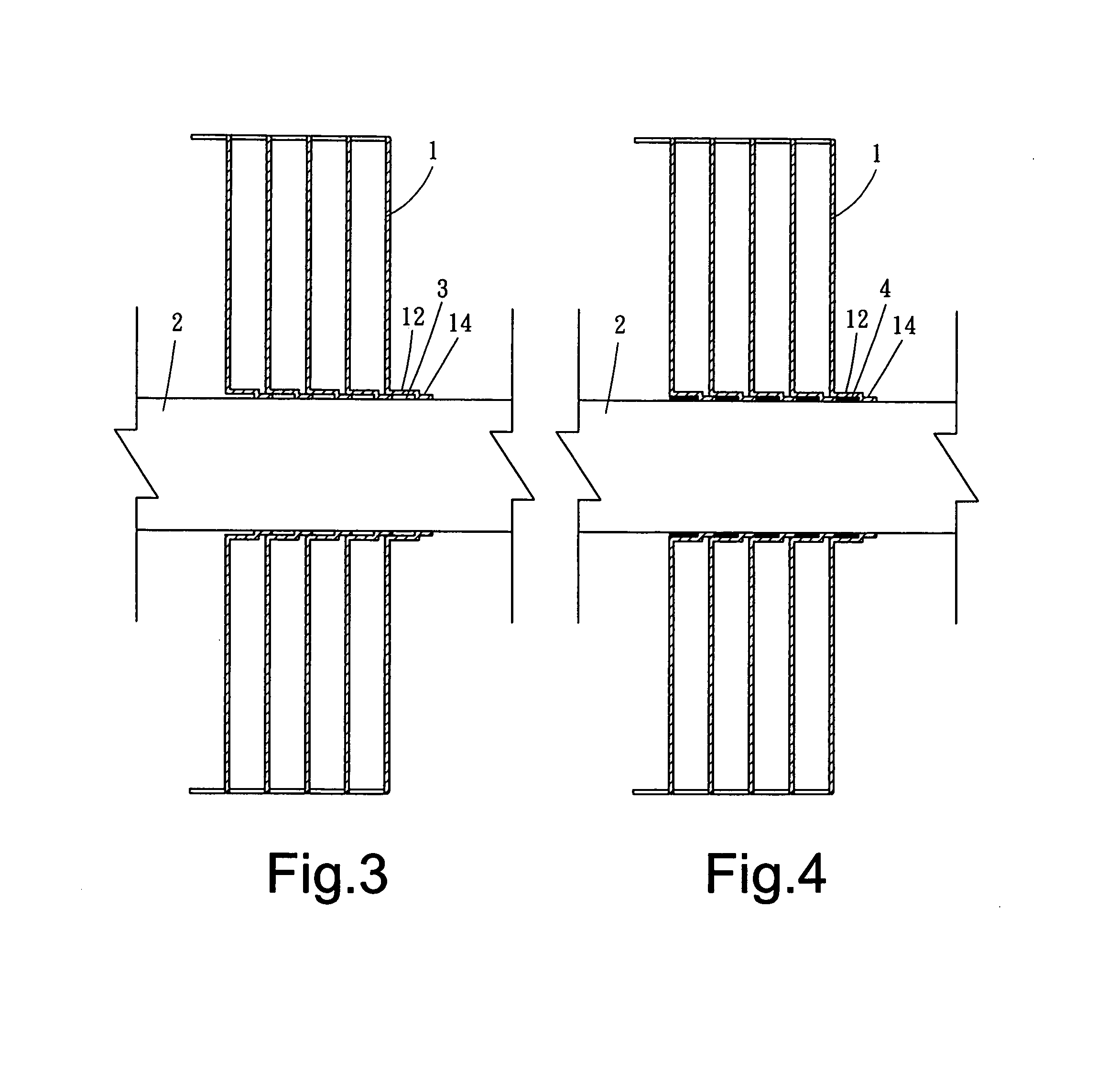
[0016]Referring to FIGS. 3 and 4, when the plural cooling fins 1 are successively penetrated by the heat pipes 2 at the through holes 11 and arranged in juxtaposition, a small part of the stair-shaped bent portion 12 of one said cooling fin 1 is nestingly placed over the extending section 14 of an underlying said cooling fin 1.

[0017]Thereby, a closed accommodating space 3 is defined between the stair-shaped bent portion 12 and the exten...


PUM


Abstract

An assembled configuration of cooling fins and heat pipes facilitates filling of a thermal interface material between contact surfaces of the cooling fins and the heat pipes and enhances stability of the cooling fins. The configuration is characterized in that each of the juxtaposed cooling fins is formed at an end thereof contacting the heat pipes with a bent portion having at least two sections so as to define an accommodating space for the thermal interface material and an extending section, wherein the accommodating space can be sufficiently filled with the thermal interface material and the extending section can be nestingly overlapped by an adjacent cooling fin, so as to effectively prevent the thermal interface material from leaking out and enhance stability of the assembled cooling fins.

Description

BACKGROUND OF THE INVENTION[0001]1. Technical Field[0002]The present invention relates to a finned heat sink device and, more particularly, to an assembled configuration of cooling fins and heat pipes of a finned heat sink device which facilitates filling of a thermal interface material between the cooling fins and the heat pipes and enhances stability of the cooling fins.[0003]2. Description of Related Art[0004]In order to achieve rapid heat dissipation from a central processing unit (CPU) and a power supply of a general computer or from an electronic element of an electronic equipment, a finned heat sink is usually provided where heat is generated. The finned heat sink may be further provided with heat pipes penetrating cooling fins of the finned heat sink, so that heat is transferred from the heat source to the cooling fins through thermal conduction of the heat pipes to accelerate heat dissipation.[0005]In prior art, the cooling fins and the heat pipes are assembled by penetrati...

Claims


Application Information

Patent Timeline
Patent Type & Authority Applications(United States)
IPC IPC(8): F28D15/04
CPCF28F1/32F28D15/02
Inventor YANG, CHIEN-LUNG
Owner SUPER MICRO COMP
Learn More