Magnetic Coupling Mobile Robot

a mobile robot and magnetic coupling technology, applied in the direction of steering control, non-vehicle mounted steering control, braking system, etc., can solve the problems of requiring enormous power to drive the wheels, unable to achieve free-sliding movement along the surface being inspected, and prior art solutions that are not shown

Active Publication Date: 2010-08-26
TECNOMAC
View PDF5 Cites 52 Cited by
  • Summary
  • Abstract
  • Description
  • Claims
  • Application Information

AI Technical Summary

Problems solved by technology

Prior art solutions exhibit one notable disadvantage.
Whilst being able to function, they require enormous power to drive the wheels in order to overcome the magnetic field which tends to immobilize the wheels.
It is therefore diffic

Method used


Image

  • Magnetic Coupling Mobile Robot
  • Magnetic Coupling Mobile Robot
  • Magnetic Coupling Mobile Robot

Examples


Embodiment Construction

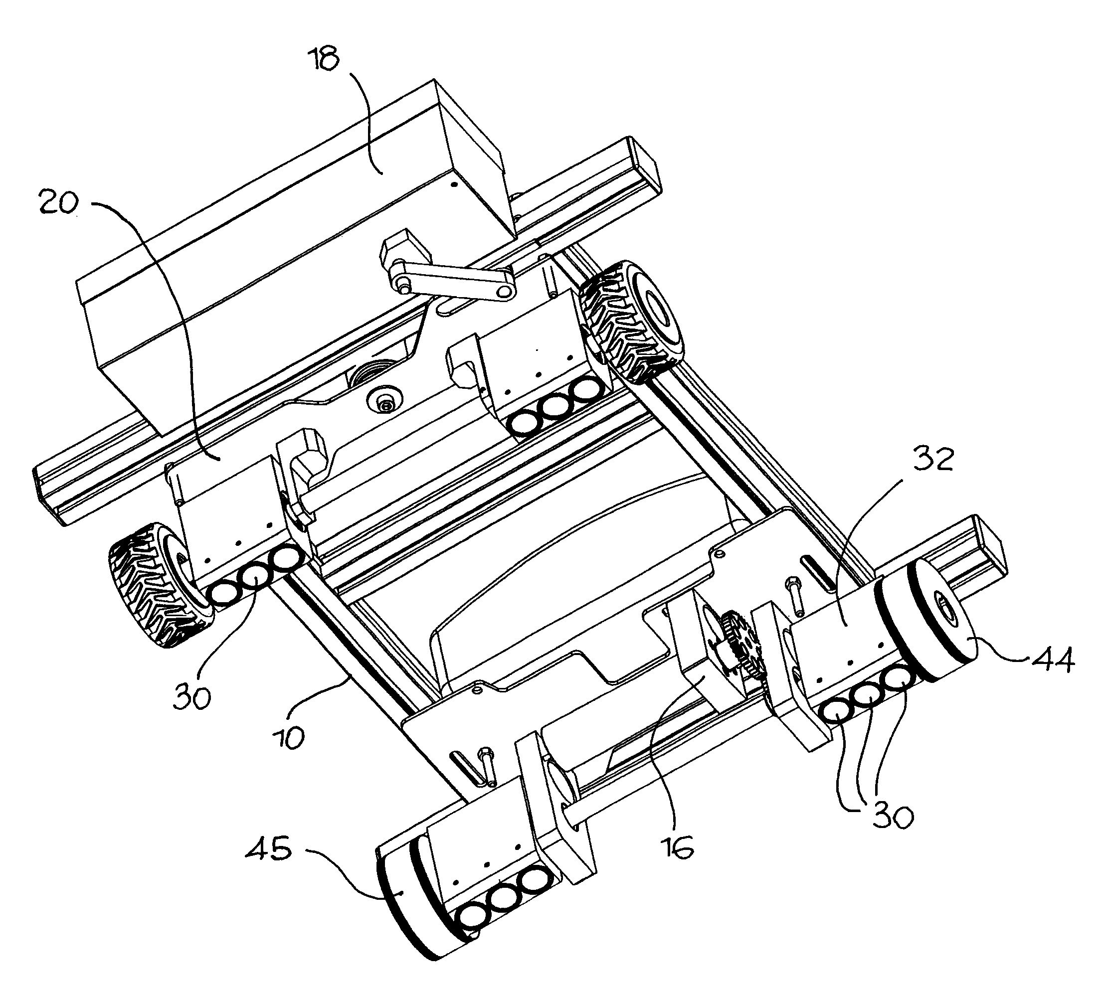
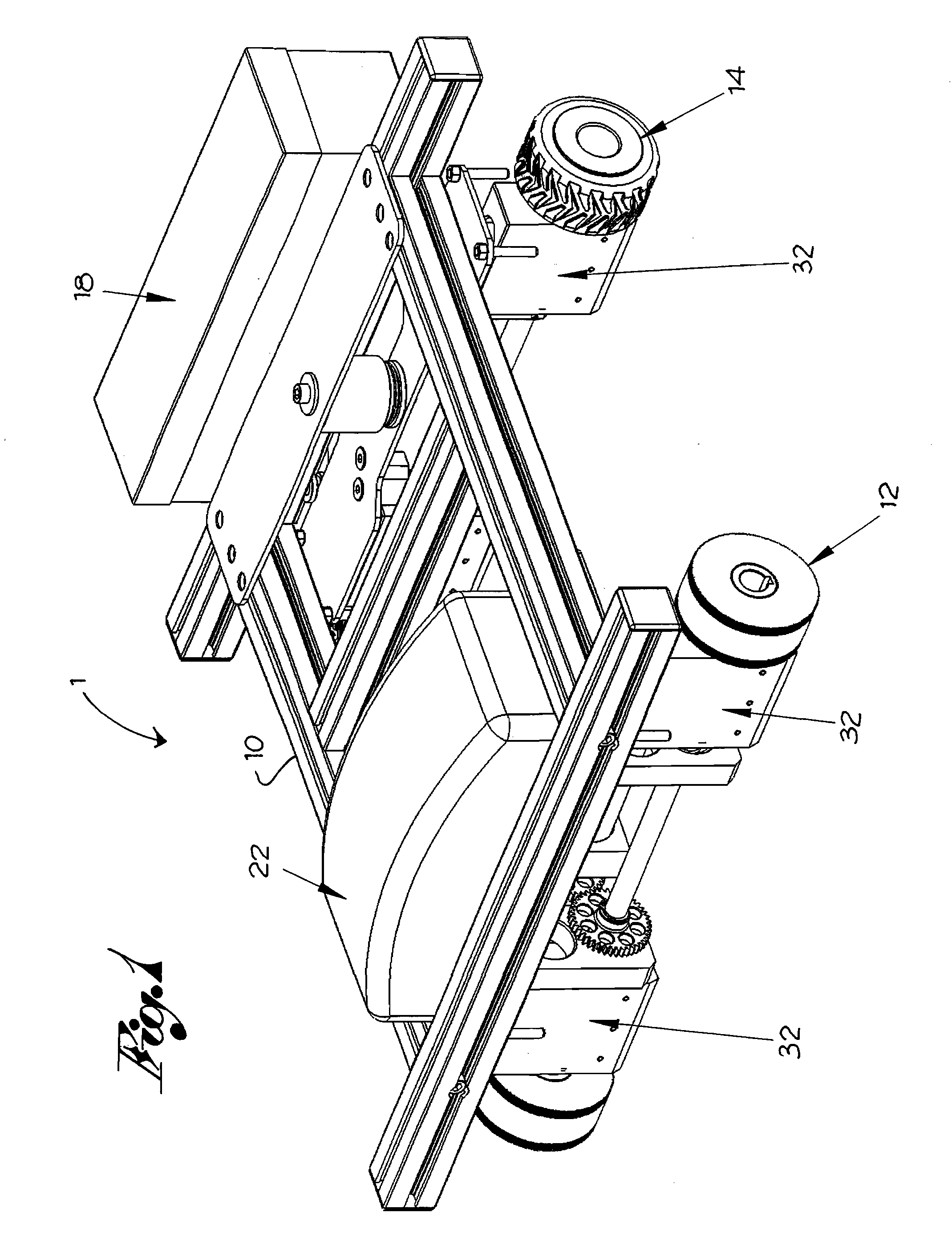
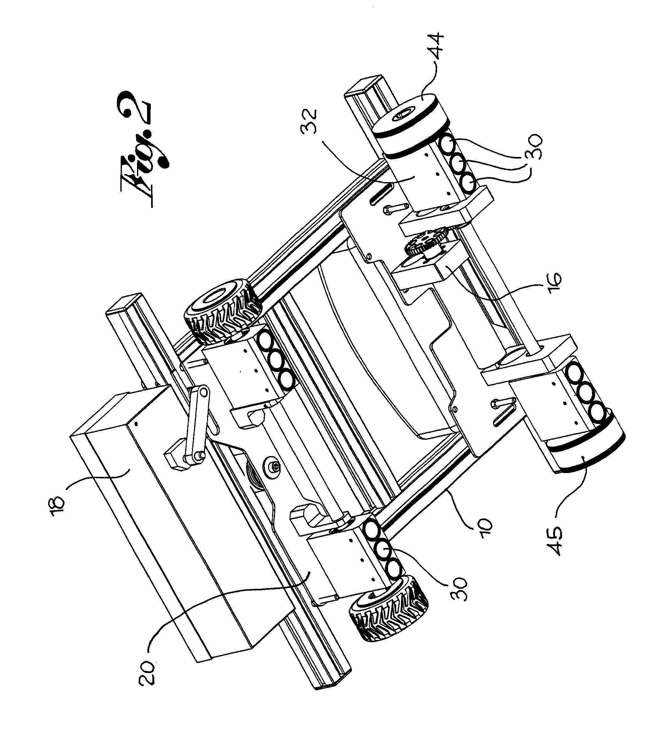
[0024]With reference to the above figures, numeral reference 1 globally indicates a mobile robot with magnetic coupling according to the invention.

[0025]Robot 1 includes a frame 10 with wheels 12, 14 enabling the robot to slide over a resting surface 2 which is highly magnetically permeable, for example a ferromagnetic material. The robot 1 is in the form of a mobile carriage able to move over a surface, for example a piece of sheeting to be inspected.

[0026]In accordance with a preferred embodiment, the robot 1 is fitted with at least one driving wheel 12 enabling independent movement over the surface to which it is coupled magnetically. This does not exclude the possibility of the robot described below being moved manually along the resting surface.

[0027]In accordance with a preferred embodiment, at least one driving wheel 12 is powered by a motor reduction gear 16.

[0028]Advantageously, the motor reduction gear 16 is powered electrically with continuous voltage of, for example, 12 ...


PUM


Abstract

A robot including a frame with wheels moves over a highly magnetically permeable support surface and at least one permanent magnet able to interact magnetically with, and couple the robot to, the surface. The permanent magnet is positioned so that one pole grazes the surface and is free to oscillate so that the pole always faces the surface and is a minimum distance from it.

Description

FIELD OF THE INVENTION[0001]The present invention relates to a mobile robot with magnetic coupling.[0002]In some applications in the art, surfaces to be processed or treated in various ways, for example, to be welded together, may be inspected by a robot provided with wheels allowing the robot to move along the surface. The robot is fitted with probes able to inspect the surface by detecting, for example, the quality of the process carried out.[0003]When the material of which the surface is made allows it, i.e. when it is ferromagnetic, the robot is coupled magnetically to the surface by means of permanent magnets. Thanks to this anchoring system, the robot can also climb vertically or even rotate through 360°. Therefore not only flat surfaces can be inspected, but also curved—for example cylindrical—surfaces.BACKGROUND ART[0004]Thus far, robots with magnetic coupling have been fitted with wheels which are made, at least externally, in contact with the surface, of permanent magnets ...

Claims


Application Information

Patent Timeline
IPC IPC(8): B62D1/24B60K8/00
CPCB62D57/024
Inventor LAMA, ARTURO
Owner TECNOMAC
Why Eureka
Try Eureka