Transmission system for a cycle

a transmission system and cycle technology, applied in the direction of motorcycles, cycles, transportation and packaging, etc., can solve the problems of less energy-efficient pedal power motion and the individual's inability to pedal power to negotiate hills or other inclines, and achieve the effect of convenient releasable coupling

Inactive Publication Date: 2010-08-26
CLAUSEN GREGORY N
View PDF3 Cites 7 Cited by
  • Summary
  • Abstract
  • Description
  • Claims
  • Application Information

AI Technical Summary

Benefits of technology

[0010]at least one coupling member which is releasably receivable in or on each of the driven member and the fixture to releasably connect the driven member to the fixture and thereby allow the drive means to drive rotation of the at least one driven wheel.
[0011]Accordingly, a transmission system according to the present invention allows a rider to selectively engage and disengage an auxiliary drive means from driving rotation of a driven wheel of a cycle. The present invention therefore allows a rider to retain the favourable characteristics of a pedal powered cycle, such as use of a standard derailleur, gearing system and independent pedal power, while also having the convenience of being able to selectively enable an auxiliary drive source to assist the rider drive rotation of the driven wheel. Moreover, by sensibly operating a transmission system according to the invention, a rider can minimise use of the drive unit and thereby conserve fuel, conserve engine life and minimise greenhouse gas emissions.
[0018]The driven member and the fixture are preferably arranged proximate to each other to facilitate easy releasable coupling therebetween. Typically, this necessitates the driven member and the fixture to be aligned in one or more orientations relative to the at least one driven wheel. In one embodiment, the driven member and the fixture are coaxially arranged about an axis of rotation of the at least one driven wheel. Of course, most cycle wheels include an axle at the axis of rotation. Accordingly, it is preferable for the driven member and the fixture to be coaxially arranged about the axle of the at least one driven wheel.

Problems solved by technology

While this drive means is very energy efficient, it can be tiring for an individual to use pedal power to negotiate hills or other inclines.
As can be appreciated, the additional resistance created by the connected transmission system can make this pedal power motion less energy efficient.

Method used


Image

  • Transmission system for a cycle
  • Transmission system for a cycle
  • Transmission system for a cycle

Examples


Embodiment Construction

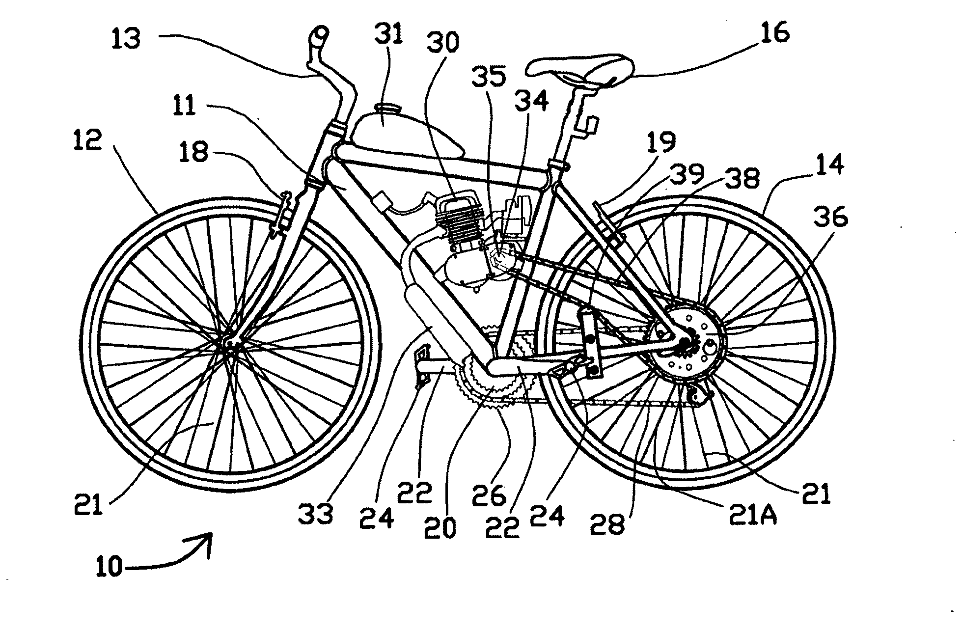
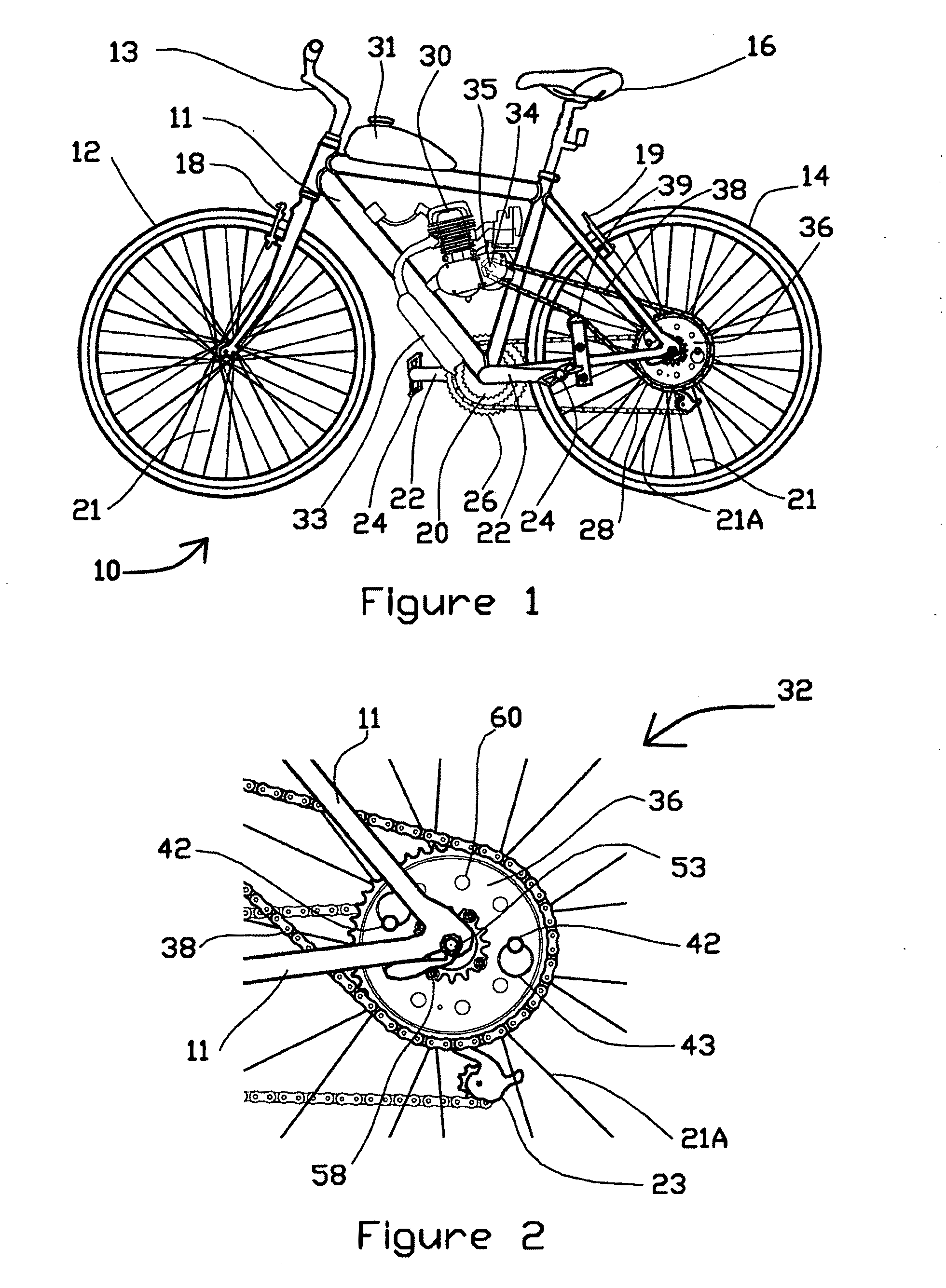
[0037]Referring firstly to FIGS. 1 to 6, there is shown a conventional bicycle 10 fitted with a transmission system 32 according to the present invention. Referring firstly to FIG. 1, it can be observed that the bicycle 10 includes a tubular frame 11 to which is connected a front wheel 12 which can be laterally directed using a steering handlebar 13, a driven wheel 14 being the rear wheel of the bicycle 10, front brakes 18, and rear brakes 19 and a seat 16 on which a rider (not shown) can be seated when riding the bicycle 10. Each of the front wheel 12 and driven wheel 14 are spoked wheels and therefore include spokes 21. The spokes 21 of the driven wheel 14 include drive-side spokes 21A being those spokes provided in the drive-motor transmission side of the driven wheel 14. The illustrated wheels 12 and 14 have a thirty-six spoke wheel configuration. In comparison, the wheel shown in FIG. 7 has a thirty-two spoke wheel configuration.

[0038]The illustrated bicycle 10 includes two act...


PUM


Abstract

A transmission system for a cycle having a drive means and at least one driven wheel. The transmission system includes a driven member operatively connected to the drive means, the driven member being selectively driven by the drive means; at least one fixture fixedly connected to the at least one driven wheel; and at least one coupling member which is releasably receivable in or on each of the driven member and the fixture to releasably connect the driven member to the fixture. The transmission system is configured so that one or more coupling members can be selectively used to releasably connect the driven member to the fixture and thereby allow the drive means to drive rotation of the at least one driven wheel.

Description

FIELD OF THE INVENTION[0001]The present invention generally relates to a transmission system for a cycle. The invention is particularly applicable for use in transmitting power from an auxiliary drive means to at least one wheel of a pedal powered bicycle and it will be convenient to hereinafter disclose the invention in relation to that exemplary application. However, it is to be appreciated that the invention is not limited to that application and could be used in any type of cycle arrangement where it is desirable to use one or both of a motorised drive means and pedal power to drive the rotation of a wheel.BACKGROUND OF THE INVENTION[0002]The following discussion of the background to the invention is intended to facilitate an understanding of the invention. However, it should be appreciated that the discussion is not an acknowledgement or admission that any of the material referred to was published, known or part of the common general knowledge as at the priority date of the app...

Claims


Application Information

Patent Timeline
Patent Type & Authority Applications(United States)
IPC IPC(8): B62M23/02B62M1/00B62M6/25
CPCB62M7/02B62M6/25
Inventor CLAUSEN, GREGORY N.
Owner CLAUSEN GREGORY N
Why Eureka
Try Eureka