Adaptive feedback control method of fsc display

a feedback control and display technology, applied in the field of image display techniques, can solve the problems of suppressing the signal from human eyes to human brains, affecting the luminous efficiency of fsc-lcd, and the problem of color break-up (cbu), so as to reduce the sum of color difference and effectively suppress the cbu phenomenon

Inactive Publication Date: 2010-08-26
CHUNGHWA PICTURE TUBES LTD
View PDF7 Cites 4 Cited by
  • Summary
  • Abstract
  • Description
  • Claims
  • Application Information

AI Technical Summary

Benefits of technology

[0018]Accordingly, the present invention is directed to a technique for synchronously updating both liquid crystal and backlight gray-scale information according to an input image content, so that the color brightness originally distributed in various color fields is concentrated in a single color field, which significantly reduces a color difference sum as compared with each pixel of an input frame, thus effectively suppressing the CBU phenomenon.

Problems solved by technology

A conventional liquid crystal display (LCD) utilises a color filter to achieve full-color effects, but the luminous efficiency thereof is not desirable.
However, generally, the critical problem of a conventional FSC-LCD lies in a color break-up (CBU) problem.
The CBU problem is caused by a relative movement between an object in an image and eyes of an observer, that is, during a saccade interval of human eyes, a signal from human eyes to human brains is suppressed due to a saccadic suppression.
Unfortunately, in this method, when the frequency of the green color field is lower than 50 Hz, the human eyes can perceive a flicker phenomenon, and as a result, the frame quality is deteriorated.
However, when the backlights are all turned on, color filters are still required for achieving the full-color effects of the image.
However, in order to acquire the color of the fourth sub-field, the statistics of the image must be analyzed first, which is not only time consuming, but also increases the calculation capacity.

Method used


Image

  • Adaptive feedback control method of fsc display
  • Adaptive feedback control method of fsc display
  • Adaptive feedback control method of fsc display

Examples


Embodiment Construction

[0055]Although several preferred embodiments are cited in the present invention for illustration, the accompanying drawings and the following specific implementations are merely taken as preferred embodiments of the present invention. It should be noted that, the following specific implementations are merely examples of the present invention, but not intended to restrict the present invention in the drawings and specific implementations.

[0056]Hereinafter, embodiments of a method of the present invention are specifically described.

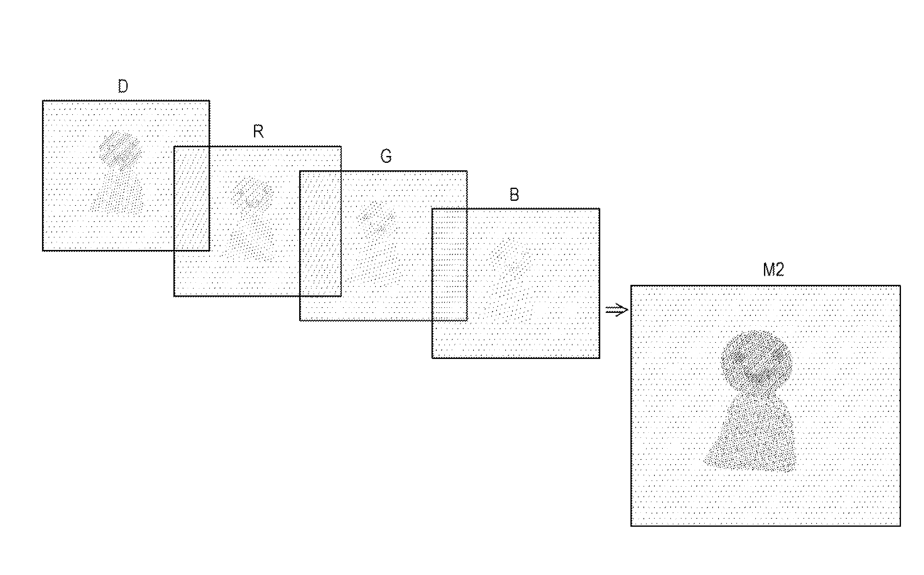
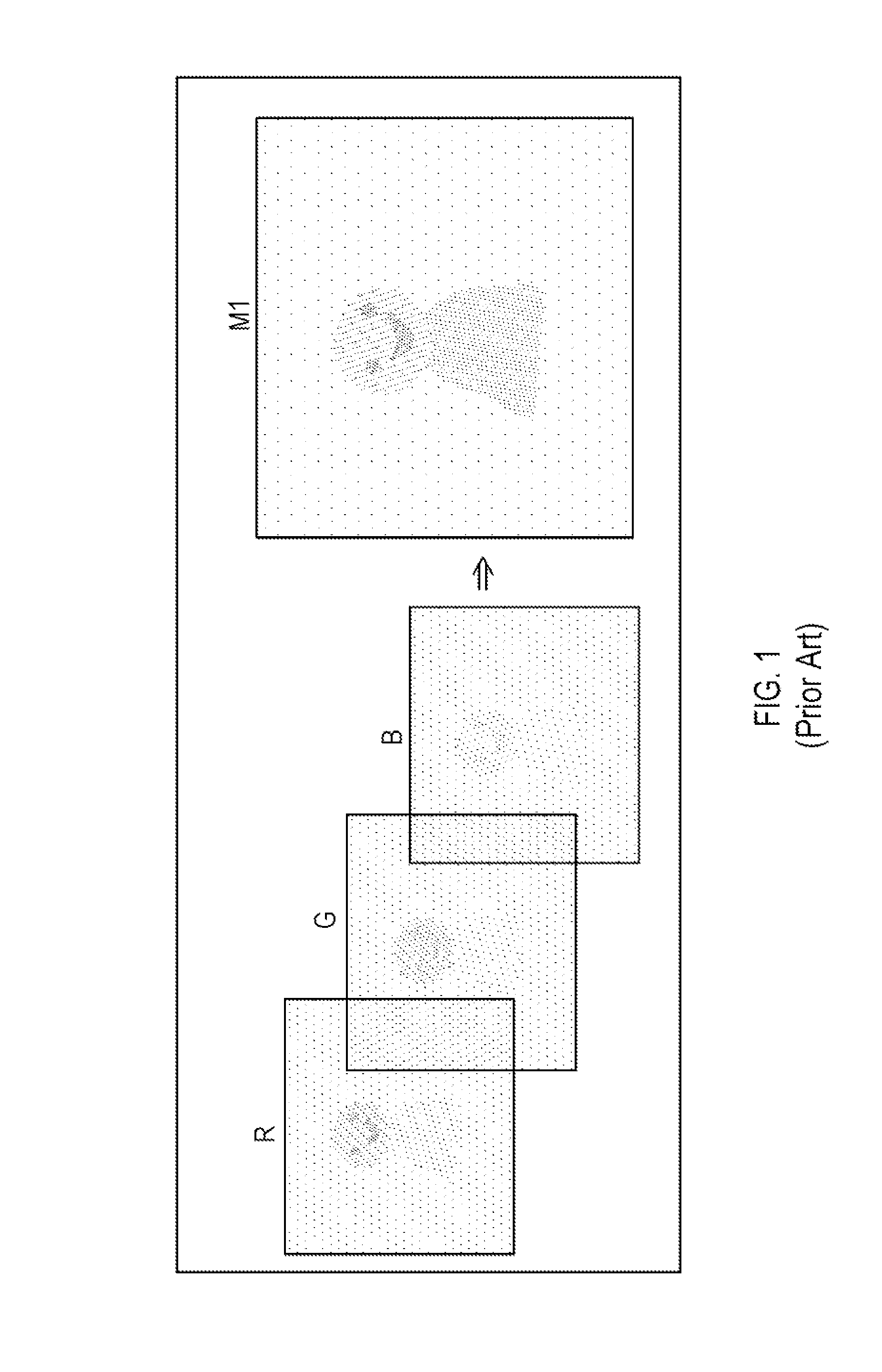
[0057]In order to particularly suppress the CBU, three primary color sub-fields R, G and B are mainly concentrated on a dominated color field (D-field) D, as shown in FIG. 3. Through rearranging the color fields, an intensity of the primary colors is enhanced, and clearly-distinguished primary color fields are concentrated into a single mixed color field, thereby forming an image M2 capable of suppressing the CBU. Therefore, as compared with the conventiona...


PUM


Abstract

An adaptive feedback control method of a field sequential color display includes converting gray-scale values of a three primary color field of an input image into gray-scale values of a new three primary color field and a dominated color field (D-field); performing sampling; performing a pixel by pixel sum operation for each separated color through color gamut conversion to obtain a color difference sum; performing a feedback control at a bit precision to obtain a minimum color difference sum; and then performing a liquid crystal/backlight synchronization step of synchronizing a liquid crystal signal and a backlight gray-scale value of the input image; or dividing the input image into a plurality of blocks; performing feedback control operations; obtaining a minimum sum in each block to serve as an optical backlight value, thereby reducing a CBU phenomenon, and minimizing or controlling the generated CBUs to reduce the operation loads.

Description

CROSS-REFERENCE TO RELATED APPLICATIONS AND PATENTS[0001]This application claims priority as a CIP application based on prior Non-Provisional application Ser. No. 12 / 391,804, filed Feb. 24, 2009, which is incorporated by reference.BACKGROUND OF THE INVENTION[0002]1. Field of Invention[0003]The present invention relates to an image displaying technique, and more particularly to an adaptive feedback control method, suitable for performing an adjustment in real time according to a frame content to achieve a backlight color field with a minimum image color difference, thereby alleviating a color break-up (CBU) phenomenon of a field sequential color (FSC) display.[0004]2. Related Art[0005]A conventional liquid crystal display (LCD) utilises a color filter to achieve full-color effects, but the luminous efficiency thereof is not desirable. Based on a fast-response liquid crystal panel, such as an optically compensated bend (OCB) mode, and a backlight source, such as a high-efficient light...

Claims


Application Information

Patent Timeline
Patent Type & Authority Applications(United States)
IPC IPC(8): G09G5/10
CPCG09G3/3413G09G3/3611G09G2340/06G09G2320/0242G09G2320/0646G09G2310/0235
Inventor CHEN, CHUN-HOCHIEN, SHIH-HSUNLIN, FANG-CHENGHUANG, YI-PAISHIEH, HAN-PINGTAI, WEN-CHIHCHIOU, SHIAN-JUN
Owner CHUNGHWA PICTURE TUBES LTD
Why Eureka
Try Eureka