Tying tool for shoelace

Inactive Publication Date: 2010-09-02
WHANG JONG O
View PDF6 Cites 7 Cited by
  • Summary
  • Abstract
  • Description
  • Claims
  • Application Information

AI Technical Summary

Benefits of technology

[0023]According to a device for binding shoelaces of the present invention, since the device including a first binding portion having a receiving member and a binding member which are separated from each other by pressure, a second binding portion to insure the union for the end of the shoelaces, and third binding portion to maintain and adjust the union for the lower end of the shoelaces, the shoelaces can be safely bound and released. Products applied with this device may be expected the satisfaction of its users and its competitive power.
[0024]In the first binding portion, since the union between the receiving member and the binding member is released by only pressing it toward the instep of user's foot, the convenience in use can be greatly enhanced, the damage thereof by means of overdue

Problems solved by technology

However, the conventional shoes having the above structure has problems in that they are troublesome and require lots of time in wearing because a user should untie their shoelaces, release them toward both sides and pull and tie them, and also in that during walking the shoelace are untied, and knots of the shoelaces is disordered and then their fine view is not good.
However, in the device for binding shoelaces afore filed by the present applicant, the adjusting lever 121b provided on both sides of the body 11

Method used


Image

  • Tying tool for shoelace
  • Tying tool for shoelace
  • Tying tool for shoelace

Examples


Embodiment Construction

[0059]The above described objects, characteristics, and advantages of the present invention will become apparent from the following detailed description.

[0060]Hereinafter, a device for binding shoelaces according to the present invention will be described in detail with reference to the accompanying drawings.

[0061]Note that the same components or parts are shown to have same reference numbers in the drawings. In describing the present invention, any related known function or structures are not described in detail so as to not vague the gist of the present invention.

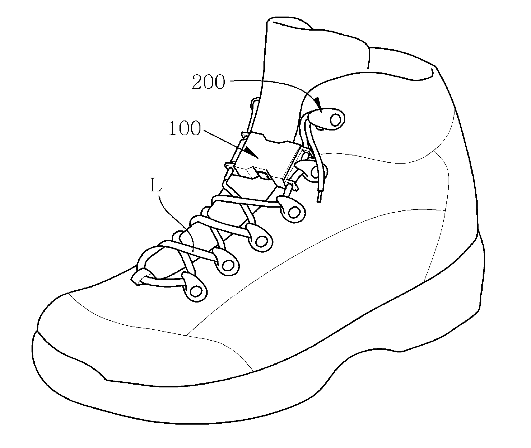
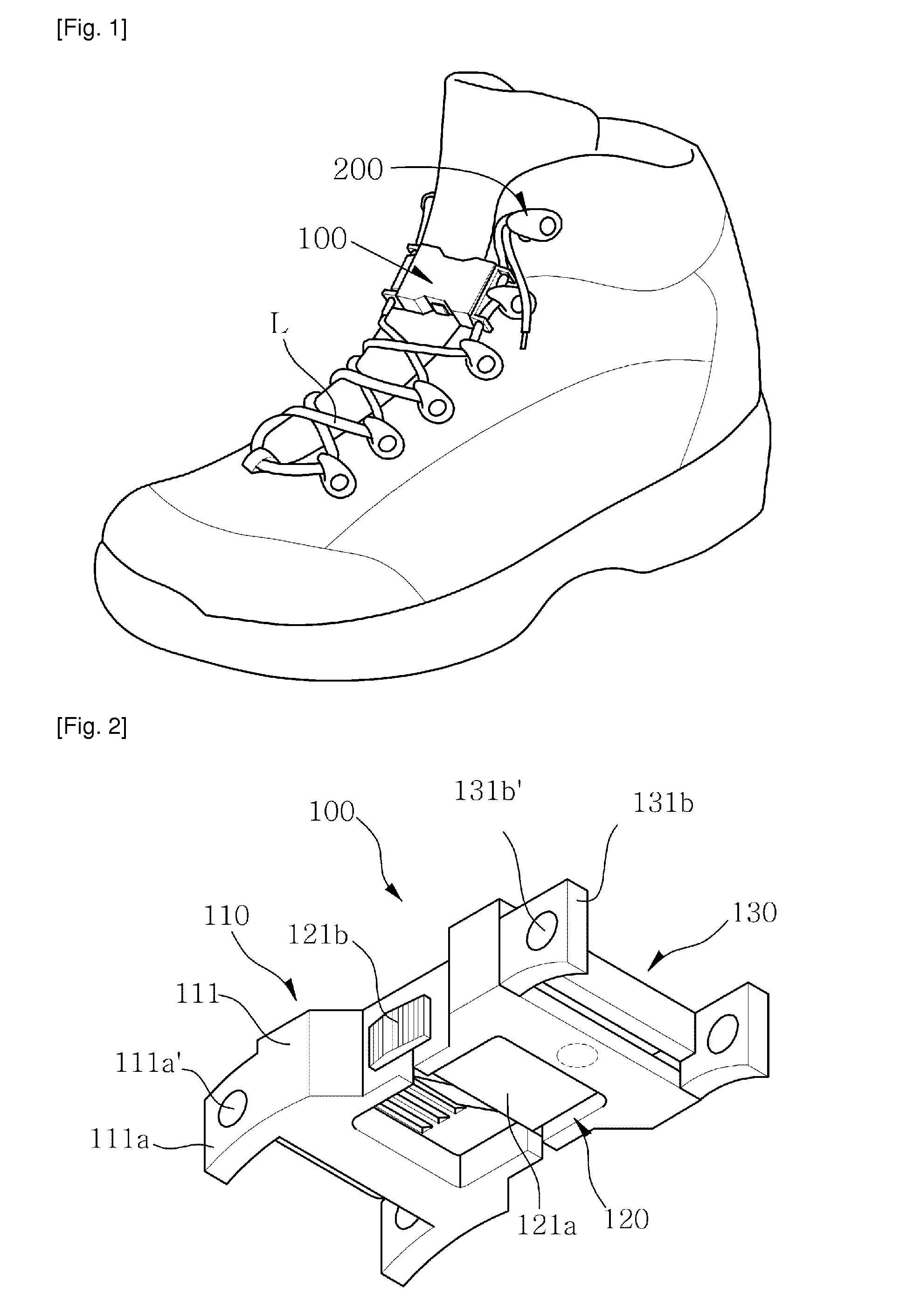
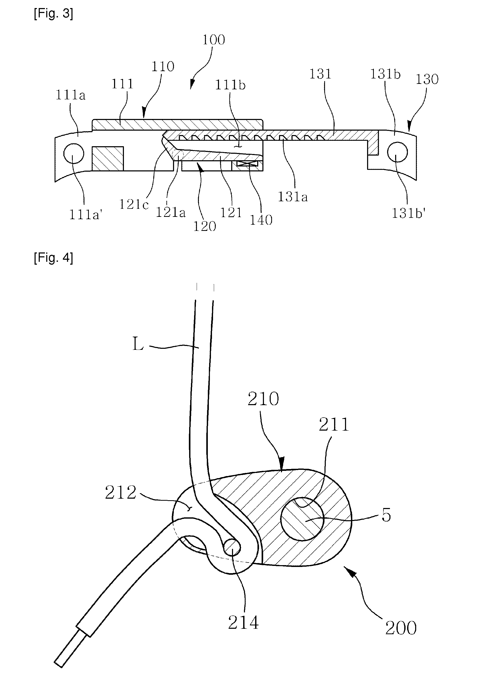
[0062]FIG. 5 is a perspective view schematically illustrating shoes applied with a first binding portion in the device for binding shoelaces according to the present invention.

[0063]FIG. 10 is a perspective view schematically illustrating shoes applied with a second binding portion in the device for binding shoelaces according to the present invention.

[0064]FIG. 14 is a perspective view schematically illustrating shoes ap...


PUM


Abstract

A device for binding shoelaces is disclosed. The device is provided on shoes having hook rings oppositely formed on both side of the instep thereof, the device comprising a binding member having a clutching plate formed with a clutching recess with a constant distance according to one side thereof; a receiving member having an opened slot at one side thereof so that the clutching plate is inserted in, a magnetic body attached on one side of the slot, and an installing recess formed in the direction vertical to the slot; and an adjusting member having a board typed pressing plate rotatably installed in the installing recess to be selectively attached to the magnetic body and receiving the pressing force, and a stopper protruded from one side of the pressing plate and selectively clutched in the clutching recess. According to a device for binding shoelaces of the present invention, the shoelaces may be safely bound and released since the device including a first binding member having a receiving member and a binding member which are separated from each other by pressure, a second binding member to insure the union for the end of the shoelaces, and third binding member to maintain and adjust the union for the lower end of the shoelaces. Products applied with this device may be expected the satisfaction of its users and its competitive power.

Description

TECHNICAL FIELD[0001]The present invention relates to a device for binding shoelace provided on shoes to bind the instep of a foot, more specifically relates to a device for binding shoelace having enhanced convenience in use, the device including a first binding portion in which an inserting member is easily detachable by press given to a rotating stopper provided in a receiving member which is outwardly exposed, a second binding portion to firmly grasp the shoelaces from each other, and a third binding portion to be able to easily adjustably grasp the shoelaces on the instep of the foot.BACKGROUND ART[0002]In general, shoes are one of the necessities of life used as a moving means, and recently their usage is greatly increased by the increasing of man and woman's social activities and the increasing of leisure living due to the working conditions for the five-day workweek. The shoes have lots of kinds for their use, however most shoes are provided with detachable shoelaces.[0003]T...

Claims


Application Information

Patent Timeline
IPC IPC(8): A43C7/04A43C3/00A43C11/00A43C5/00
CPCA43C7/00A43C7/08A43C11/008A43C11/146A43B1/0054Y10T24/375A43C1/04Y10T24/3724Y10T24/3705Y10T24/3742A43C1/003
Inventor WHANG, JONG O.
Owner WHANG JONG O
Why Eureka
Try Eureka