A mooring connector

a technology of mooring connectors and connectors, applied in the direction of ropes and cables for vehicles/pulleys, anchoring arrangements, shackles, etc., can solve the problems of reducing down time, and reducing so as to reduce the likelihood of a connector being damaged, reduce the surface area or the mass of material, and release safely

Active Publication Date: 2019-10-10
BALLTEC
View PDF7 Cites 9 Cited by
  • Summary
  • Abstract
  • Description
  • Claims
  • Application Information

AI Technical Summary

Benefits of technology

[0011]In this way, the present invention is configured to use a load applied to a connector that could otherwise damage the connector to assist in its unlocking from a complementary connector, when the connector and complementary connector are released from one another whilst under the load. Specifically, this reduces the likelihood of a connector being damaged when released under load. It is in a state of partial release that a connector is likely to be damaged when released under load, when the load carried by the connector may be supported by partially engaged components and so the load is supported by a reduced surface area or mass of material. However, with the present invention, load applied to the connector when in a partially unlocked state causes the connector to rapidly move into an unlocked state. This allows the complementary connector to separate without the potentially damaging load being taken up by the connector in a partially unlocked state.
[0012]The present invention therefore provides a connector that can be safely released from its locking with a complementary connector whilst the connector and the complementary connector are under a high load pulling them apart. In particular, embodiments of the present invention can be released from their complementary connectors when the load is a high percentage of their minimum break load (MBL), such as up to 75%, compared to conventional connectors that must be released at 30% of their MBL to avoid damage. Accordingly, when used as a release under load connector that, for example, secures a drilling rig to the seabed, as described above, the present invention can allow an operator to delay release of the drilling rig under inclement weather conditions, allowing the weather to get worse and increasing the tension across the mooring line, in order to more accurately determine if release is necessary. This may lead to reduced down time and thus increased revenue and profits. In addition, since existing release under load connectors must be released at around 30% of their MBL, they are typically massively over specified to accommodate for this, which increases their cost, weight and complexity. As embodiments of the present invention can be released at up to 75% of their MBL, they are cheaper, lighter and less complicated than conventional release under load connectors with an equivalent maximum release load.

Problems solved by technology

Specifically, this reduces the likelihood of a connector being damaged when released under load.
It is in a state of partial release that a connector is likely to be damaged when released under load, when the load carried by the connector may be supported by partially engaged components and so the load is supported by a reduced surface area or mass of material.
This may lead to reduced down time and thus increased revenue and profits.
In addition, since existing release under load connectors must be released at around 30% of their MBL, they are typically massively over specified to accommodate for this, which increases their cost, weight and complexity.

Method used


Image

  • A mooring connector
  • A mooring connector
  • A mooring connector

Examples


Embodiment Construction

[0031]In order that the invention may be more clearly understood an embodiment thereof will now be described, by way of example only, with reference to the accompanying drawings, of which:

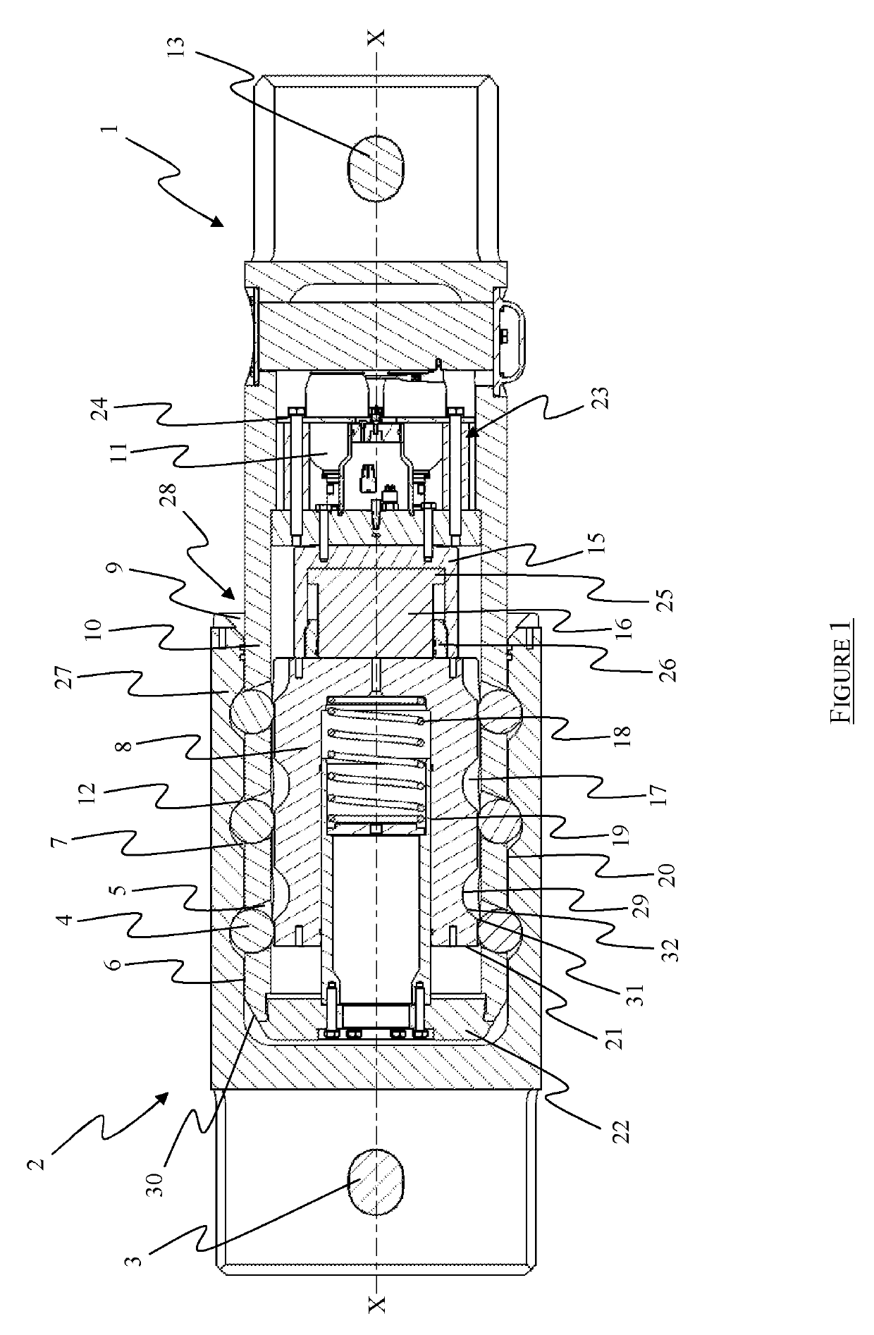
[0032]FIG. 1 is a side cross-sectional view of a connector received in a complementary connector, with the locking member in a fully locked position and the connector locked to the complementary connector;

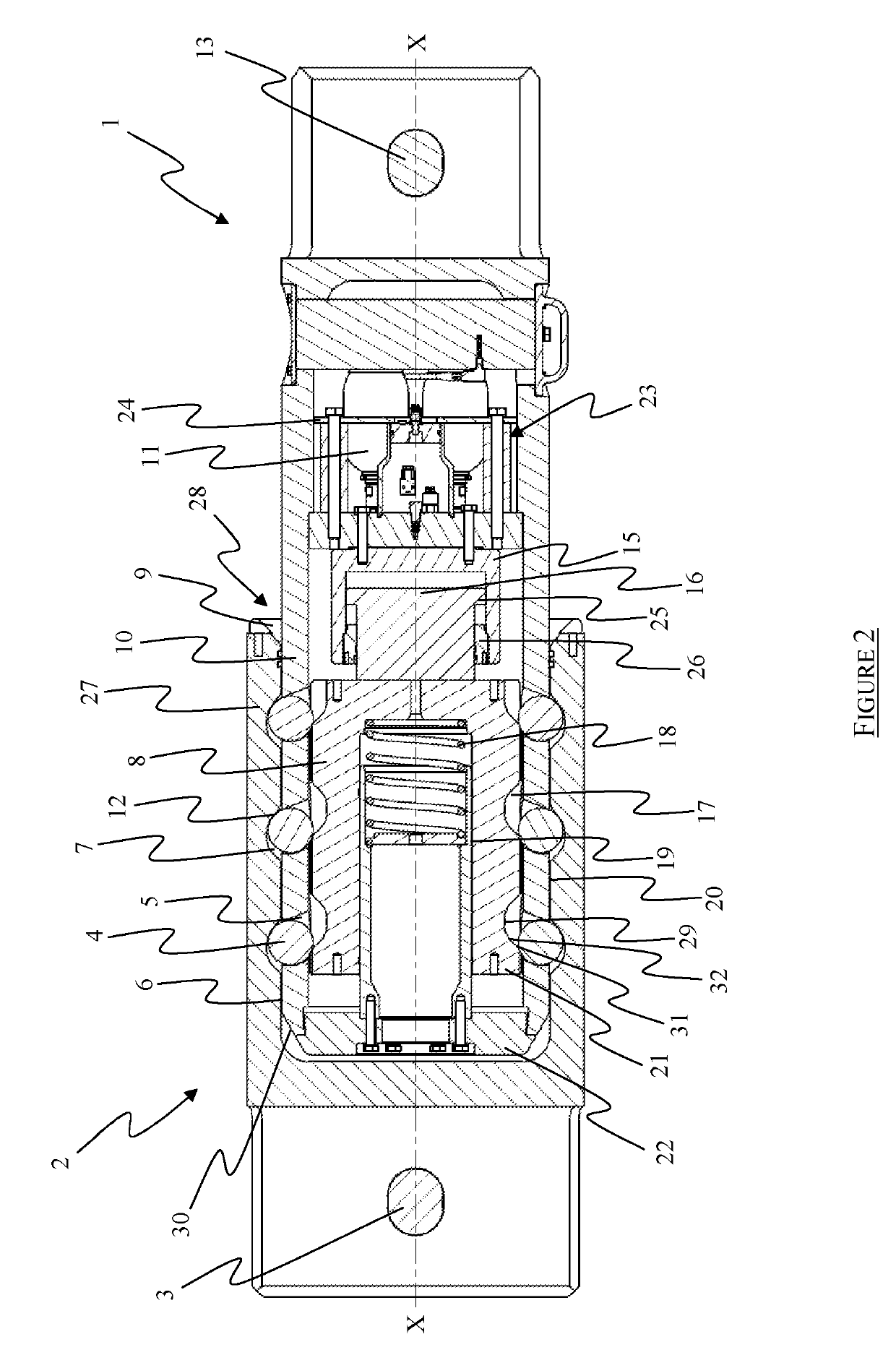
[0033]FIG. 2 is a side cross-sectional view of the connector and complementary connector of FIG. 1, with the locking member in a partially unlocked position and the connector locked to the complementary connector;

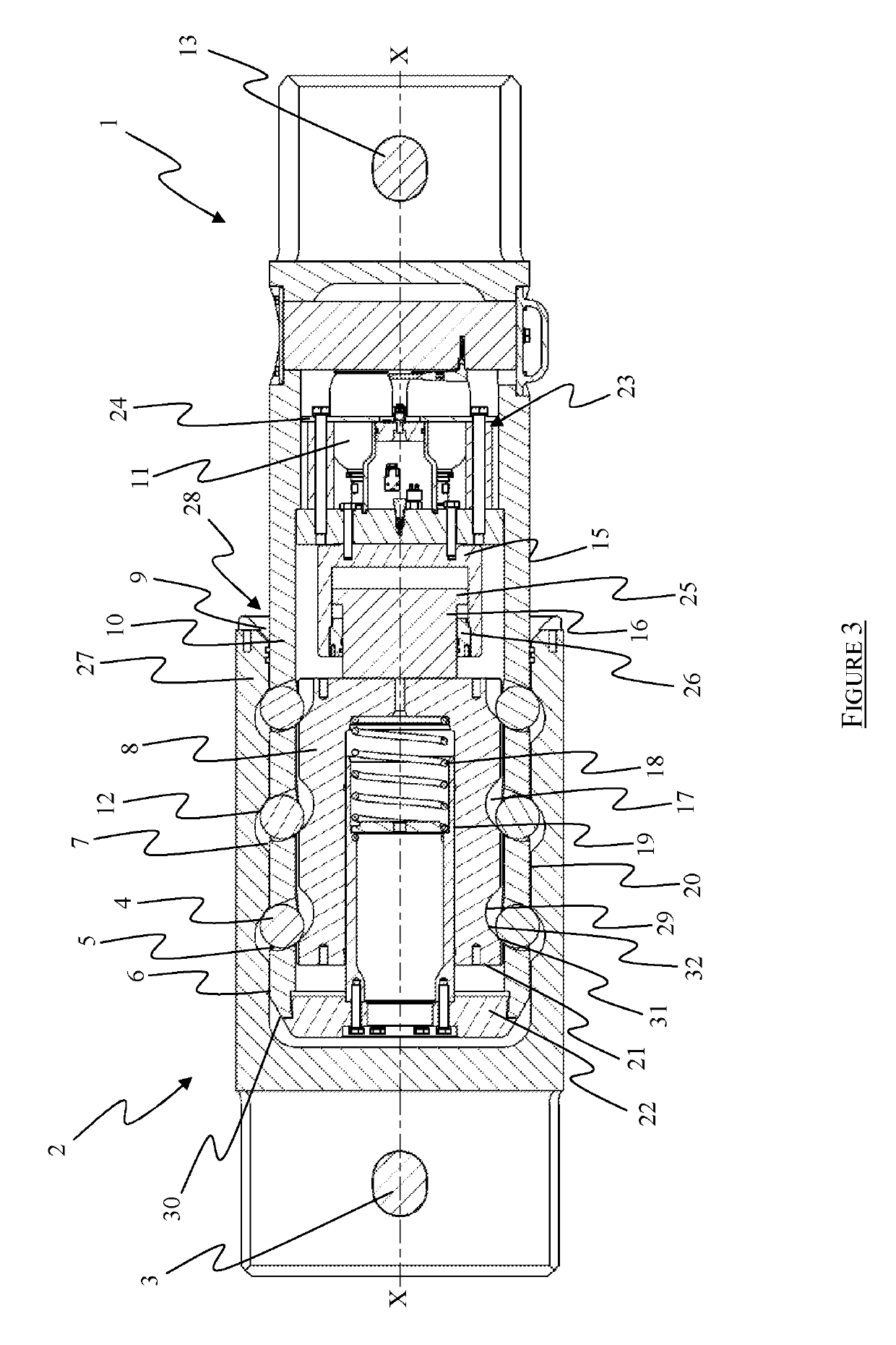
[0034]FIG. 3 is a side cross-sectional view of the connector and complementary connector of FIG. 1, with the locking member in a partially unlocked position;

[0035]FIG. 4 is a side cross-sectional view of the connector and complementary connector of FIG. 1, with the locking member in a partially unlocked position and spaced from the piston;

[0036]FIG. 5 is a side cross-sectional view of the...


PUM


Abstract

A connector adapted for release under load from a complementary connector. The connector having a locking element for engagement with the complementary connector to lock the complementary connector to the connector; and a locking member moveable from a locked position to an unlocked position. The locking member operative to permit the / each locking element to lock the complementary connector to the connector when in the locked position and operative to allow the / each locking element to release the complementary connector when in the unlocked position. The locking member and locking element arranged such that when the connector is locked to the complementary connector and the locking member is in a partially unlocked position, a load applied to the / each locking element causes the / each locking element to urge the locking member towards its fully unlocked position, thereby unlocking the complementary connector from the connector.

Description

TECHNICAL FIELD OF THE INVENTION[0001]The present invention relates to a connector, and in particular to a mooring connector configured to release under load from its locking with a complementary connector. The connector may be a mooring connector or for use in lifting or other operations.BACKGROUND TO THE INVENTION[0002]In one application, mooring connectors are used to connect drilling rig mooring lines together to secure a drilling rig to the seabed. A secured drilling rig may need to be released and moved to avoid inclement weather such as a storm. Economically, it is desirable to release the mooring connectors and begin to move the drilling rig only if absolutely necessary, so as to minimise down time. In practice, this means that one would typically wait for a storm to build up to a certain degree before releasing the drilling rig.[0003]“Release under load” mooring connectors are designed for this purpose and are therefore configured to function when the connected mooring line...

Claims


Application Information

Patent Timeline
Patent Type & Authority Applications(United States)
IPC IPC(8): F16G11/10E21B41/10B63B21/04
CPCB63B2021/004E21B41/10B63B21/04F16G11/108B63B21/502B63B2021/003B63B21/00B63B21/50F16G11/00F16G15/04
Inventor JACKSON, JONATHANTEIXEIRA, MARCOPARRY, WILLIAM DAVID LOTON
Owner BALLTEC
Why Eureka
Try Eureka