Magnetic drapery track

a magnetic drapery and track technology, applied in the field of window or door coverings, can solve the problems of affecting the installation speed of the gypsum-based drywall, the damage of the hardware if installed incorrectly, and the cumbersome installation of mounting hardware, etc., and achieve the effect of quick installation

Active Publication Date: 2011-11-08
HOME DEV OF CLEARWATER CORP
View PDF24 Cites 9 Cited by
  • Summary
  • Abstract
  • Description
  • Claims
  • Application Information

AI Technical Summary

Benefits of technology

[0017]An important object of the invention s to provide a drapery holder that can be installed quickly and in the absence of tools, in the absence of brackets installed with tools, and in the absence of making holes or bores in walls or window jambs.
[0018]Another important object is to provide a drapery holder that stays in place during normal use but which safely releases from its mount if subjected to unusually heavy downward forces.

Problems solved by technology

Mounting hardware is often cumbersome to install because the hardware items are typically quite small and difficult to work with.
The hardware if installed incorrectly damages the gypsum-based drywall, plasterboard, or other wall or window jamb covering.

Method used


Image

  • Magnetic drapery track
  • Magnetic drapery track

Examples


Embodiment Construction

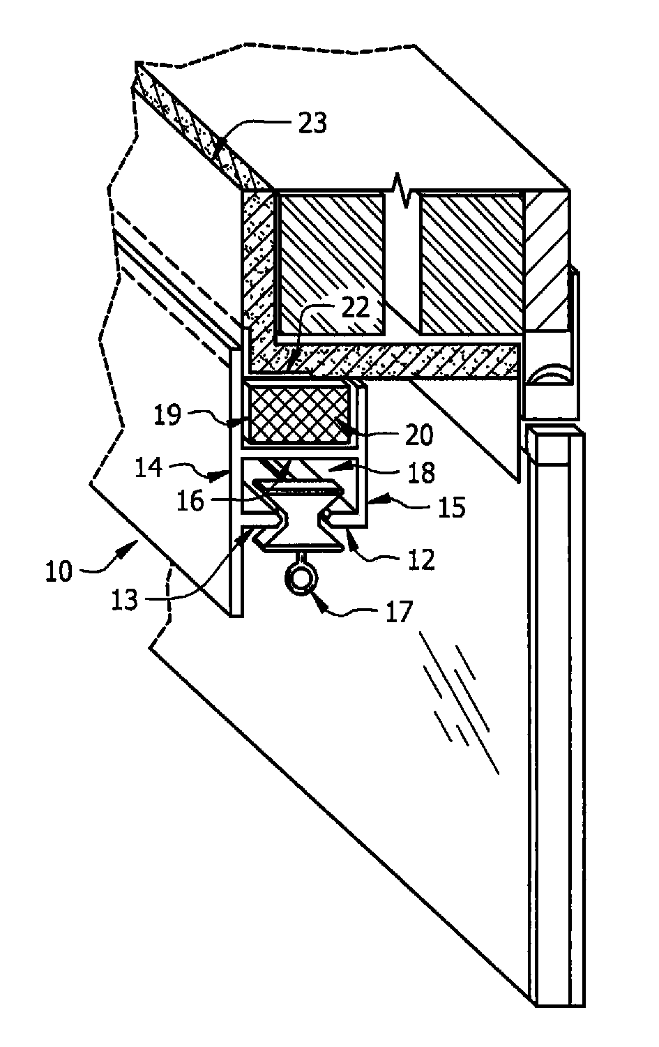
[0024]FIG. 1 depicts an illustrative embodiment of the novel structure which is denoted as a whole by the reference numeral 10.

[0025]Novel magnetic drapery track 10 includes vertical front wall 14 and vertical back wall 15. Said walls are parallel to one another and are interconnected to one another by horizontal bottom wall 16 that has the same longitudinal extent as said front and back walls.

[0026]Horizontal flange 13 is formed integrally with front wall 14 and horizontal flange 12 is formed integrally with back wall 15. Flanges 12 and 13 are co-planar and extend toward one another in an inboard direction relative to their respective front and back walls 14 and 15. Flanges 2 and 13 extend the entire length of their associated walls 14, 15. The respective inboard ends of flanges 12 and 13 are spaced apart from one another by a predetermined distance.

[0027]A plurality of drapery carriers is slidingly captured between flanges 12 and 13. Only one of said carriers, denoted 17, is depic...


PUM


Abstract

A drapery holder releasably engages a header jamb of a window. A vertical front wall and back wall are disposed in parallel relation to one another and are interconnected to one another by a horizontal bottom wall. Co-planar horizontal flanges are formed integrally with the front wall and the back wall and extend toward one another. Respective inboard ends of the horizontal flanges are spaced apart from one another to capture drapery carriers that are slideable along the extent of the horizontal flanges under the control of a drapery control apparatus. A channel is formed by the horizontal bottom wall and respective upper ends of the front and back walls and a plurality of magnets is positioned within the channel. Each magnet magnetically engages ferrous materials that form a part of the header jamb so that the drapery holder is releasably secured to the header jamb by a magnetic field.

Description

CROSS-REFERENCE TO RELATED APPLICATIONS[0001]This application is a continuation of and claims priority to Provisional Application No. 60 / 923,654 filed Apr. 16, 2007 by the same inventor, entitled “Magnetic Drapery Track Without Mounting Hardware.” That application is hereby incorporated into this application by reference.BACKGROUND OF THE INVENTION[0002]1. Field of the Invention[0003]This invention relates, generally, to window or door coverings. More particularly, it relates to window or door coverings that are installed without the use of conventional mounting members such as screws, clips, brackets and the like.[0004]2. Description of the Prior Art[0005]In the construction of openings including but not limited to windows and sliding doors and doorways it is desirable to provide coverings such as textiles to shield not only the elements but to provide privacy as well. Most conventional vertical blinds or draperies are suspended from some form of track. These tracks require direct ...

Claims


Application Information

Patent Timeline
Patent Type & Authority Patents(United States)
IPC IPC(8): E06B3/46
CPCA47H1/04A47H1/06A47H15/04A47H2201/01Y10T16/3797Y10T16/379Y10T16/376Y10T16/375Y10T16/373Y10S52/04
Inventor KONECEK-HUGHES, KATHLEEN M.
Owner HOME DEV OF CLEARWATER CORP
Why Eureka
Try Eureka