Decapping device for vacuum blood collection tube

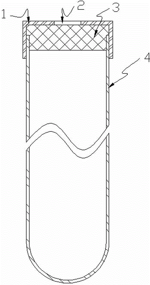
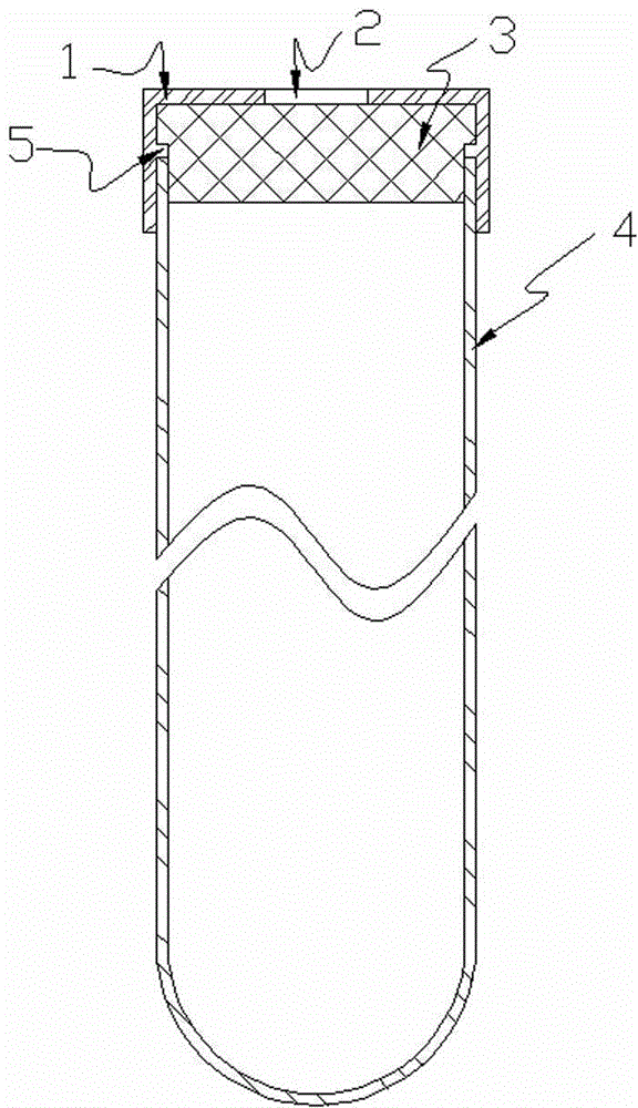
A vacuum blood collection tube and cap removal technology, which is applied in the disassembly of threaded caps and finger-like grasping hooks, etc., can solve the problems of damage to the storage tube 4, accelerated falling of the storage tube 4, uneven restraint of the clamping plate on the cap 1, etc. , to achieve the effect of simple mechanical action, safe cap removal, and reduced cap removal force

Inactive Publication Date: 2015-06-10
QIANFOSHAN HOSPITAL OF SHANDONG
View PDF8 Cites 8 Cited by
  • Summary
  • Abstract
  • Description
  • Claims
  • Application Information

AI Technical Summary

Problems solved by technology

This structure needs to use the constraint of the clamp to realize the cap removal, but it is affected by the centrifugal force on the one hand, and on the other hand, the constraint of the clamp on the cap 1 is not uniform, and it cannot guarantee that the force of the clamp on th

Method used


Image

  • Decapping device for vacuum blood collection tube
  • Decapping device for vacuum blood collection tube
  • Decapping device for vacuum blood collection tube

Examples


Embodiment Construction

[0035] It is foreseeable that in the present invention, the vacuum blood collection tube is placed vertically and the cap is removed up and down.

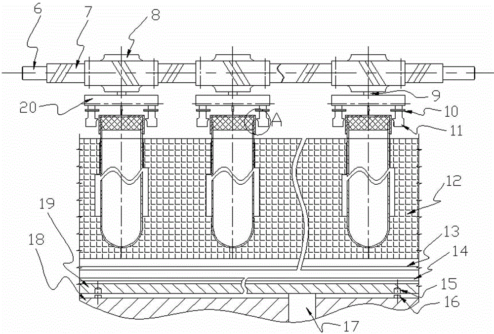
[0036] It can be foreseen that, for example, the end-face spiral disk 20 is a disk-shaped member, so that the concept of radial direction can be determined, and at the same time, centrifugal and centripetal can be determined.

[0037] For the meshing of the gear 8 and the rack 7, it is predictable that the modulus of the two is the same, but it should be noted that the size of the gear will cause the transmission ratio to change, so when the movement of the rack is determined, gears of different sizes will Rotation angles of different sizes are generated, and at the same time, the size of the gear and the transmission of torque can also be understood by those skilled in the mechanical field. Therefore, the size of the gear can be adjusted according to specific needs to obtain an appropriate torque.

[0038] Regarding the guide of t...


PUM


Abstract

The invention discloses a decapping device for a vacuum blood collection tube. The decapping device comprises a rack, a group of gears, a group of end-surface helical disks, pressure heads, a test tube rack and a decapping power component, wherein the test tube rack is provided with at least one row of vacuum blood collection tube positioning units, the number of each column of vacuum blood collection tube positioning units is the same as that of the gears, a non-return part is formed in each vacuum blood collection tube positioning unit after the vacuum blood collection tube is inserted; the decapping power component is connected with the test tube rack and drives the test tube rack to move up and down. With the adoption of the decapping device, decapping can be realized safely, reliably and quickly through reduction of the decapping force.

Description

technical field [0001] The invention relates to a device for removing the cap of a vacuum blood collection tube. Background technique [0002] More and more vacuum blood collection tubes are used in hospitals for blood collection. According to incomplete statistics, in 2013 alone, the number of vacuum blood collection tubes used in my country exceeded 6 billion. Before blood sample analysis, especially in the analysis on the automatic centrifuge, it is required to remove the cap of the vacuum blood collection tube. In the early days, the cap was manually removed. The efficiency of blood testing is obviously unacceptable to hospitals and patients. [0003] In view of this, there has been a capping device for vacuum blood collection tubes in recent years. The design of the uncapping device must first consider the shape and structure characteristics of the vacuum blood collection tube, such as figure 1 As shown, it is the structural principle of a vacuum blood collection tub...

Claims


Application Information

Patent Timeline
IPC IPC(8): B67B7/14
CPCB67B7/14
Inventor 张怀凤刘长虹武贞
Owner QIANFOSHAN HOSPITAL OF SHANDONG
Why Eureka
Try Eureka