Shoe Sole with Reinforcement Structure

a technology of reinforcement structure and shoe sole, which is applied in the field of shoe sole with a reinforcement structure, can solve the problems of inhibiting the free movement of the foot, reducing the flexural rigidity, and significantly increasing the flexural rigidity. eix, small flexural rigidity, and increasing the flexural rigidity

Active Publication Date: 2010-09-02
ASICS CORP
View PDF18 Cites 65 Cited by
  • Summary
  • Abstract
  • Description
  • Claims
  • Application Information

AI Technical Summary

Benefits of technology

[0045]In contrast, the beam structure shown in (e) of FIG. 1 does not function as a combined beam, hence a smaller flexural rigidity E·IX as shown in (h) of FIG. 1, during the initial period when the load W is small, e.g., when walking. Therefore, an upthrust is less likely to be felt on the arch of the foot. As the load increases, the structure goes through the transitional period ΔT to thereafter reach a state where the structure is close to being a combined beam, upon which the flexural rigidity E·IX increases significantly. Therefore, when an excessive load W is applied to the foot, the rigidity increases, and the deflection δ of the beams decreases. As a result, the function of preventing the lowering (drop) of the arch of the foot, etc., is significantly enhanced.
[0046]In (e) of FIG. 1, both of the beams 10 and 20 are provided with engagement elements. Even without such engagement elements, as long as the structure is such that the first beam 10 comes into contact with the second beam 20 as the load W is applied to the first beam 10, the beams 10 and 20 can at least exert the flexural rigidity E·I2 of a layered beam (about twice E·IZ set forth above), the structure can serve to suppress the lowering of the arch to some extent.

Problems solved by technology

However, they fail to disclose a structure in which the vertically-spaced members cooperate with each other so that the rigidity against the bending or twisting is significantly varied as necessary.
Excessively protecting a foot against such a steady load will result in the wearer feeling an upthrust on the arch or will inhibit the free movement of the foot.
On the other hand, a foot may sometimes receive an excessive load, which can impart a substantial burden to the foot, and it is important to protect the foot from such an excessive load.

Method used


Image

  • Shoe Sole with Reinforcement Structure
  • Shoe Sole with Reinforcement Structure
  • Shoe Sole with Reinforcement Structure

Examples


first embodiment

[0097]A first embodiment of the present invention will now be described with reference to FIGS. 2A to 6C. In this and subsequent figures, the arrow F denotes the front direction of the shoe, and the arrow B denotes the rear direction of the shoe.

[0098]General Structure of Shoe Sole:

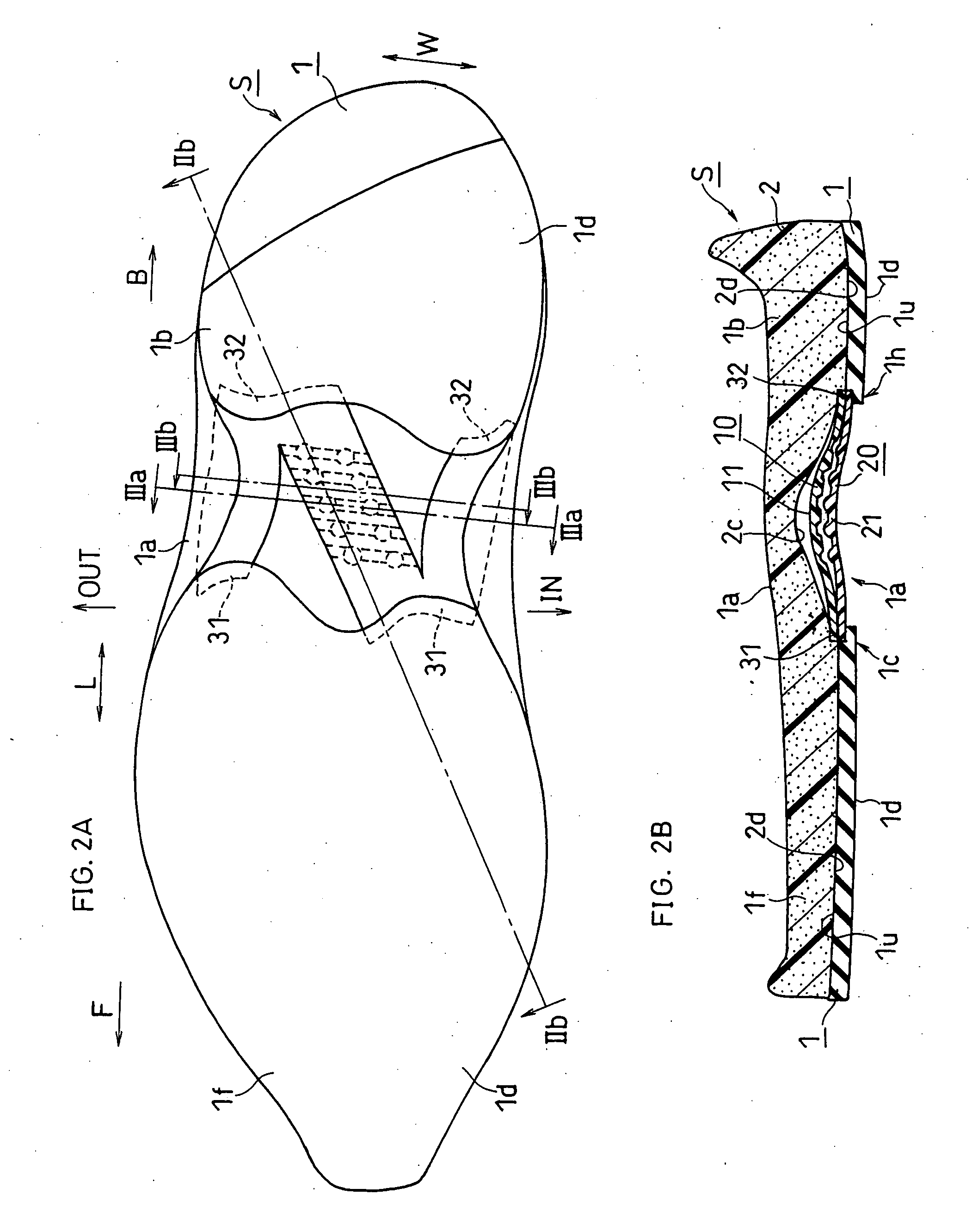
[0099]FIGS. 2A and 2B show a shoe sole S being in a non-worn state where the shoe is not put on a foot.

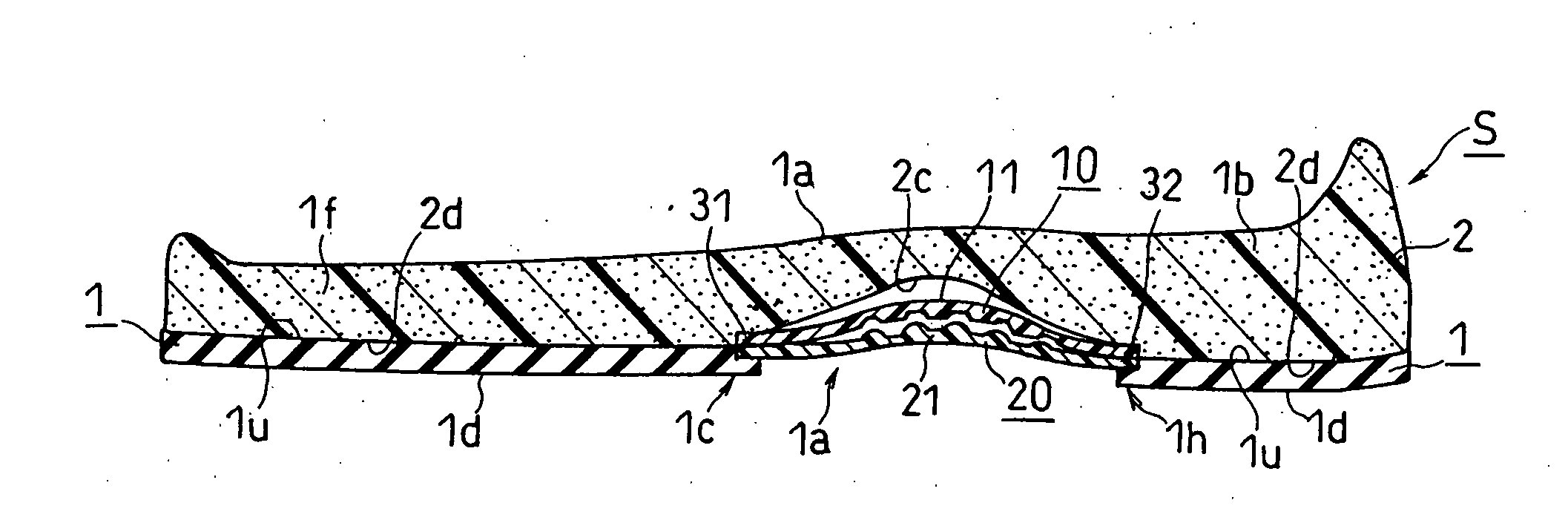
[0100]As shown in FIGS. 2A and 2B, the shoe sole S includes an outer sole 1, a mid sole (the shock absorbing layer) 2, and first and second reinforcement members (an example of the first and second members) 10 and 20 for reinforcing a middle foot portion 1a of the mid sole 2.

[0101]As shown in FIG. 2A, the outer sole 1 is divided into a front foot portion 1f and a rear foot portion 1b, and the portions 1f and 1b are spaced apart from each other at the position of a middle foot portion 1a directly under the arch of the foot. The portions 1f and 1b of the outer sole 1 each have a ground contact surface 1d t...

second embodiment

[0137]A second embodiment of the present invention will now be described with reference to FIGS. 8A to 10C.

[0138]As shown in FIG. 8B, the shoe sole of the present embodiment includes a shock absorbing layer (an example of the first member) 10A formed by using a foamed resin for absorbing the impact upon landing, i.e., the mid sole 2, the reinforcement member (an example of the second member) 20, and the outer sole 1. The first deformable portion 11 of the shock absorbing layer 10A includes the first engagement elements 12 being grooves extending in the transverse direction W, and the second deformable portion 21 of the reinforcement member 20 includes the second engagement elements 22 being hemispherical protrusions.

[0139]As shown in FIGS. 9A and 9B, the first lower surface 10d of the shock absorbing member 10A faces the second upper surface 20u of the reinforcement member 20. As shown in FIG. 9A, a portion of the second medial portion 23 of the reinforcement member 20 and a portion...

third embodiment

[0149]A third embodiment of the present invention will now be described with reference to FIGS. 12A to 12C.

[0150]As shown in FIG. 12A, a first member 10B includes a shock absorbing layer 2A formed by using a foamed resin, and a film or plate 15 of a non-foamed resin secured to the lower surface of the shock absorbing layer 2A. The second member 20 is formed by a second plate having a greater thickness than that of the film or plate 15.

[0151]Otherwise, the structure is similar to that of the second embodiment described above, and like elements are denoted by like reference numerals and will not be further described or shown in the drawings.

[0152]Non-Worn State:

[0153]In the non-worn state shown in FIG. 12A, a first lower surface 15d of the film 15 of the first member 10B is spaced apart from the second upper surface 20u of the second deformable portion 21 of the second member 20 in the vertical direction.

[0154]Under First Load:

[0155]As shown in FIGS. 12B and 12C, when the downward fir...


PUM


Abstract

A shoe sole of the present invention includes a first member 10 including a first deformable portion 11, and a second member 20 including a second deformable portion 21. In a non-worn state, a first lower surface 10d of the first deformable portion 11 and a second upper surface 20u of the second deformable portion 21 are substantially spaced apart from each other in a vertical direction. Under a first load, the first deformable portion 11 deflects downward, whereby the first lower surface 10d can approach the second upper surface 20u until the first lower surface 10d contacts the second upper surface 20u. Under a second load, the deformable portions 11 and 21 both deflect downward with the engagement elements 12 and 22 of the deformable portions 11 and 21 engaging with each other.

Description

TECHNICAL FIELD[0001]The present invention relates to a shoe sole with a reinforcement structure including a so-called “shank” (a reinforcement member).BACKGROUND ART[0002]Shoe soles in which a reinforcement member that is matched to the shape of the arch of the mid sole is provided in the arch portion of the shoe soles are known in the prior art, e.g., shoe soles in which a portion of the mid sole that is not attached to the outer sole does not come into contact with the ground upon landing of the outer sole. Such a reinforcement structure suppresses the deformation of the mid sole, thereby reinforcing the rigidity of the arch portion of the mid sole. Examples of such known structures (the first and second patent documents) are shown in FIGS. 15A and 15B.[0003]First Patent Document: Japanese Laid-Open Patent Publication No. 2003-19004 (FIG. 5)[0004]Second Patent Document: WO2005 / 037002A1 (Abstract)[0005]FIG. 15A is a side view of a shoe sole disclosed in Japanese Laid-Open Patent P...

Claims


Application Information

Patent Timeline
Patent Type & Authority Applications(United States)
IPC IPC(8): A43B13/18A43B13/42
CPCA43B7/142A43B13/141A43B13/125A43B13/181A43B13/146
Inventor NISHIWAKI, TSUYOSHIOOTSUKA, YOSUKEKISO, SATOSHI
Owner ASICS CORP
Why Eureka
Try Eureka