Inkjet printer

a technology of inkjet printer and spring, which is applied in the direction of printing, other printing apparatus, etc., can solve the problems of increasing product costs, increasing process steps, and complex structure for holding a plurality of springs, and achieves the effect of convenient assembly

Inactive Publication Date: 2008-11-18
FUNAI ELECTRIC CO LTD
View PDF14 Cites 20 Cited by
  • Summary
  • Abstract
  • Description
  • Claims
  • Application Information

AI Technical Summary

Benefits of technology

[0008]An object of the present invention is to provide an inkjet printer with a carriage On which an ink cartridge is securely installed, with a number of components, Which can be readily assembled.
[0010]In this configuration, the back end face of the ink cartridge is pressed forward by the back end face pressing lever using the biasing force of the spring provided between the pressing member and the cover body. On the other hand, since the pressing member is formed in a bending shape, the top face of the ink cartridge is pressed by the top face pressing lever downward by means of the reaction force of the force created by the back end face pressing lever pressing the back end face of the ink cartridge. In this manner, the ink cartridge is pressed from two directions using one spring and one pressing member, so that the ink cartridge can be securely fixed in the carriage. As a result, the number of components of the carriage can be reduced. In addition, the assembly process steps can be reduced.
[0011]Preferably, in the inkjet printer as described above, a first end portion side from the pivot of the top face pressing lever is formed to have smaller flexural rigidity as compared with the second end portion side from the pivot. With this configuration, the second end portion side from the pivot of the top face pressing lever can reliably transmit the biasing force of the spring to the back end face of the ink cartridge because of its relatively high flexural rigidity. On the other hand, the first end portion side from the pivot of the top face pressing lever may elastically deform to some extent because of its relatively small flexural rigidity. Therefore, even with some dimensional deviations of the ink cartridge or the carriage, the top face of the ink cartridge can be pressed securely.
[0012]Preferably, in the ink cartridge as described above, a stopper is provided for preventing the back end face pressing lever biased by the spring from projecting further than necessary when the cover body is opened. This stopper may be formed of an abutment body provided on the underside of the cover body in abutment with the first end portion of the top face pressing lever. Alternatively, it may be formed of a protrusion projecting laterally from the side face of the top face pressing lever in the vicinity of the second end portion, and an abutment body in abutment with the protrusion. Provision of the stopper can prevent the back end face pressing lever from unnecessarily projecting when the cover body is opened. Therefore, when the cover body is closed, the back end face pressing lever can always be brought into abutment with the back end face of the ink cartridge from a certain direction.
[0013]In accordance with the present invention, it is possible to provide an inkjet printer with a carriage on which an ink cartridge is securely installed, with a small number of components, which can be readily assembled.

Problems solved by technology

Moreover, a complicated structure for holding a plurality of springs is required.
As a result, these requirements inevitably cause increase in the product costs.
In addition, disadvantageously, two springs need to be incorporated during the assembly of the carriage in the manufacturing process of the inkjet printer, thereby increasing the process steps in the assembly operation.

Method used


Image

  • Inkjet printer
  • Inkjet printer
  • Inkjet printer

Examples


first embodiment

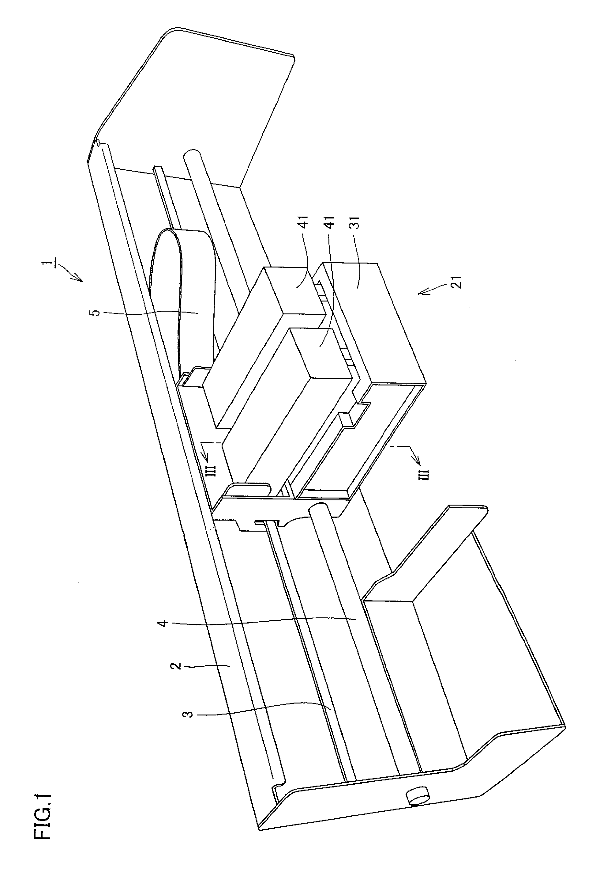
[0023]In the following, a first embodiment of the present invention will be described with reference to FIGS. 1 to 3.

[0024]Referring to FIG. 1, the structure of the main part of an inkjet printer will be described. As shown in FIG. 1, an inkjet printer in the present embodiment includes a main part 1 having a carriage 21 holding an ink cartridge and being attached movably in the horizontal direction, a guide shaft 4 holding the carriage 21, and a frame 2 to which the guide shaft 4 is fixed.

[0025]The guide shaft 4 made of metal passes through carriage 21 so that carriage 21 is guided by guide shaft 4. Carriage 21 is driven by a not-shown motor to slide horizontally along guide shaft 4. The driving force of the motor is transmitted to a belt-holding portion (not shown) on the rear face of carriage 21 through a not-shown belt extending horizontally.

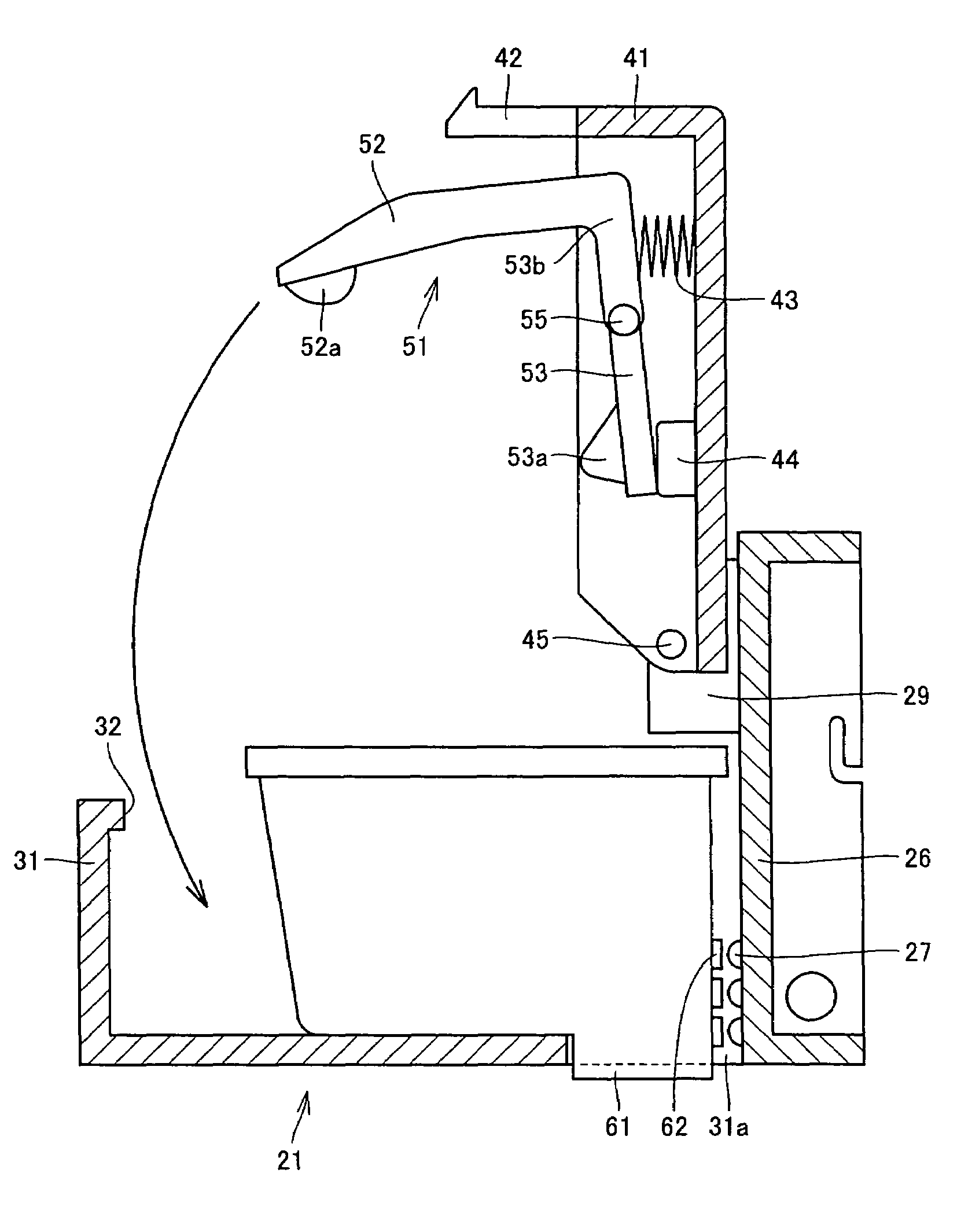
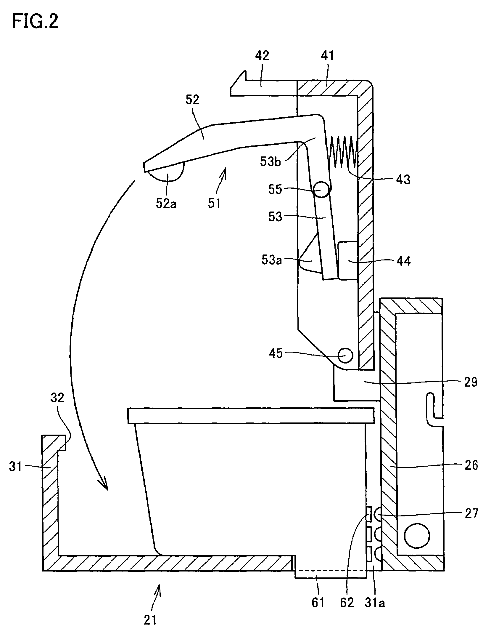
[0026]An upright base portion 26 is provided on the rear face side of carriage 21 and a cradle 31 receiving the lower portion of the ink ca...

second embodiment

[0047]A second embodiment will now be described with reference to FIGS. 5 and 6.

[0048]In the first embodiment, a stopper is formed of abutment body 44 provided on the underside of cover body 41. Instead, in the present embodiment, a stopper is formed of a protrusion 56 projecting laterally from the side surface of top face pressing lever 53 in the vicinity of second end portion 53b and an abutment body 48 in abutment with protrusion 56.

[0049]Protrusion 56 horizontally projects on both sides of pressing member 51, and abutment body 48 is provided at each position in abutment with the underside of protrusion 56. When cover body 41 is opened, the underside of protrusion 56 abuts against abutment body 48, thereby preventing spring 43 from projecting further than necessary. Protrusion 56 may be formed integrally with pressing member 51 or may be formed of a metal member passing through pressing member 51 with both ends thereof being projected. Such a stopper can also prevent unnecessary ...


PUM


Abstract

An inkjet printer includes a carriage body configured to receive an ink cartridge, an openable / closable cover body pivotally attached to the carriage body, a substantially L-shaped pressing member integrally formed of a resin and arranged on an underside of the cover body, a spring disposed between the cover body and the top face pressing lever for biasing the second end portion side of the top face pressing lever away from the carriage body, and a stopper arranged to prevent the back end face pressing lever from projecting flirter than necessary when the cover body is opened. The pressing member includes a top face pressing lever, having a first end portion configured to press a top face of the ink cartridge and a second end portion, and a back end face pressing lever joined integrally with the top face pressing lever at the second end portion thereof, the back end face pressing lever having a distal end portion configured to press a back end face of the ink cartridge. The pressing member is rotatably mounted to the cover body about a pivot defined at an intermediate portion of the top face pressing lever. The first end portion of the top face pressing lever is formed to have smaller flexural rigidity as compared with the second end portion, such that an elastic force of the first end portion causes the first end portion to press the top face of the ink cartridge when the cover body is closed.

Description

BACKGROUND OF THE INVENTION[0001]1. Field of the Invention[0002]The present invention relates to an inkjet printer, and more specifically to an inkjet printer in which an ink cartridge can be securely installed.[0003]2. Description of the Background Art[0004]In an inkjet printer, while a carriage on which an ink cartridge is installed reciprocates, the ink supplied from the ink cartridge is injected to paper thereby printing characters and the like on the paper. Since the ink cartridge is reciprocated by the carriage, it has to be installed securely in the carriage.[0005]Japanese Patent Laying-Open No. 2003-291320 discloses such a carriage of an inkjet printer. The carriage of the inkjet printer disclosed in Japanese Patent Laying-Open No. 2003-291320 has, as shown in FIG. 7, a carriage body 101 holding the lower portion of an ink cartridge 111 and a cover body 102 pressing the top surface of the ink cartridge. An arm 103 is provided on the bottom surface of the cover body 102. The ...

Claims


Application Information

Patent Timeline
Patent Type & Authority Patents(United States)
IPC IPC(8): B41J2/175B41J29/13
CPCB41J2/1752B41J2/17553
Inventor TSUJI, HIROHIKO
Owner FUNAI ELECTRIC CO LTD
Why Eureka
Try Eureka