Crash module for a rail vehicle

a technology for rail vehicles and crash modules, applied in buffers, buffer cars, railway components, etc., can solve problems such as large space requirements, global buckling with reduced energy absorption and consequently ‘riding up’, and complex design

Active Publication Date: 2010-09-02
SIEMENS MOBILITY AUSTRIA GMBH
View PDF14 Cites 19 Cited by
  • Summary
  • Abstract
  • Description
  • Claims
  • Application Information

AI Technical Summary

Benefits of technology

[0006]An object of the invention is therefore to create a device which provides a simple means of ensuring energy dissipation in crash elements by compression in the longitudinal direction of a rail vehicle even in the case of off-center load application and effectively prevents the collision partners from ‘riding up’ over one another.

Problems solved by technology

However, especially with freestanding elements it must be taken into account that, in such elements, shear forces and bending moments of the kind occurring in the event of eccentric load application can produce global buckling with reduced energy absorption and consequently ‘riding up’ of the collision partners.
The disadvantage of this solution is not only the large space requirement and complex design, but also the fact that only a reduced compression distance is available for energy dissipation.
Consequently, the rail vehicle can be damaged by transmission of impact energy.
However, in the case of small cross-sectional dimensions and the absence of lateral guidance, these elements react sensitively to eccentric load applications.
Such solutions are therefore unsuitable for overly large offset between the collision partners, as they cannot prevent twisting of the contact surfaces and ‘riding up’ of the collision partners can therefore occur.

Method used


Image

  • Crash module for a rail vehicle
  • Crash module for a rail vehicle
  • Crash module for a rail vehicle

Examples


Embodiment Construction

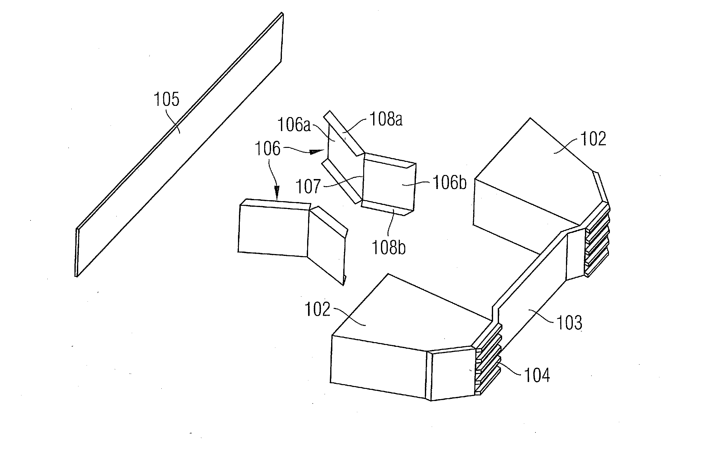
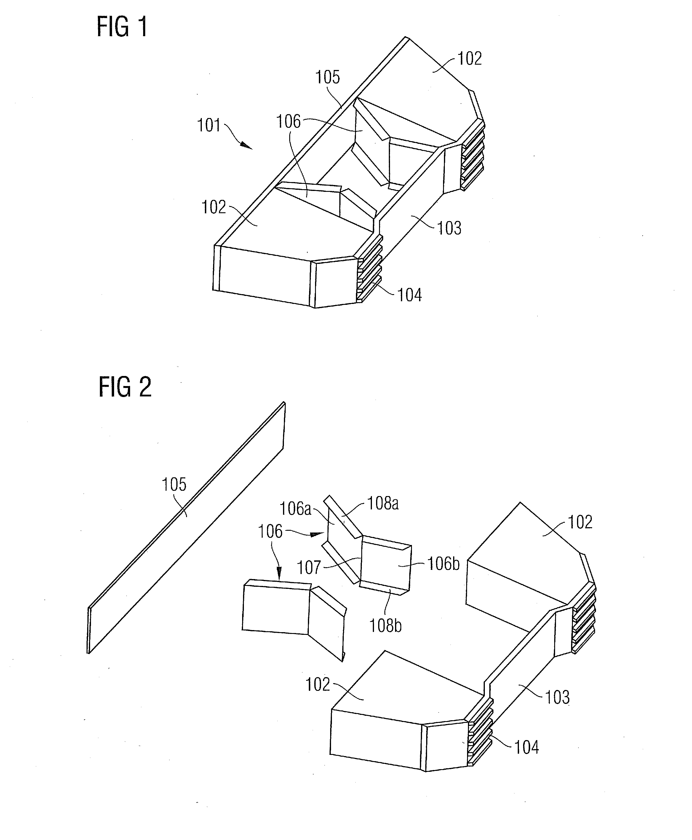
[0042]FIG. 1 shows a crash module 101 according to the invention, as used in rail vehicles, for example. Such a crash module 101 can be e.g. incorporated in the front part of a rail vehicle or can even be mounted in a freestanding manner at the front of a rail vehicle.

[0043]The crash module 101 consists of two crash elements 102 which are disposed side by side, said crash elements 102 consisting of plastically deformable material, e.g. aluminum or steel sections, foam material such as aluminum foam, or of reversible shock absorbing elements such as hydrostatic buffer elements, gas hydraulic elements or the like. The crash module 101 additionally comprises a front impact plate 103 with anti-climbing devices 104 and a rear connecting plate 105.

[0044]The front impact plate 103 is used to apply the load in the event of a collision. Although FIG. 1 shows only one exemplary embodiment, other embodiments are of course also conceivable without limiting the inventive function of the crash mo...


PUM


Abstract

A crash module for a rail vehicle is provided. The crash module includes a crash element, a frontal impact plate and a rear connecting plate, wherein a guide element is provided between the frontal impact plate and the rear connecting plate. The guide element has the form of a plate and is oriented essentially in a longitudinal direction of the rail vehicle.

Description

CROSS REFERENCE TO RELATED APPLICATIONS[0001]This application is the US National Stage of International Application No. PCT / EP2003 / 062531 filed Sep. 19, 2008, and claims the benefit thereof. The International Application claims the benefits of Austrian Application No. A1472 / 2007 AT filed Sep. 20, 2007. All of the applications are incorporated by reference herein in their entirety.FIELD OF INVENTION[0002]The invention relates to a crash module for a rail vehicle, consisting of at least one crash element which is disposed between a front impact plate and a rear connecting plate.BACKGROUND OF INVENTION[0003]In the event of a collision between two rail vehicles, a large part of the collision energy occurring is advantageously absorbed by plastic deformation in crumple zones that are deformable in a defined manner in the end areas of the rail vehicles. The crumple zones can be implemented as extensive crash areas or as crash elements with specific geometry and either incorporated in the ...

Claims


Application Information

Patent Timeline
Patent Type & Authority Applications(United States)
IPC IPC(8): B61D15/06
CPCB61G11/16B61D15/06
Inventor GRAF, RICHARDNEDELIK, ROBERTSEITZBERGER, MARKUS
Owner SIEMENS MOBILITY AUSTRIA GMBH
Why Eureka
Try Eureka