System and method for estimating and providing dispatchable operating reserve energy capacity through use of active load management

a technology of active load management and operating reserve energy capacity, applied in the field of electric power supply and generation system, can solve the problems of uneconomical storage of power, unsatisfactory fluctuations in line frequency, and additional costs for the utility

Active Publication Date: 2010-09-02
LANDISGYR INNOVATIONS INC +1
View PDF99 Cites 199 Cited by
  • Summary
  • Abstract
  • Description
  • Claims
  • Application Information

AI Technical Summary

Problems solved by technology

Such variation in demand can cause undesired fluctuations in line frequency if not timely met.
However, because power cannot be economically stored, a utility must regularly either bring new capacity on-line or take existing capacity off-line in an effort to meet demand and maintain frequency.
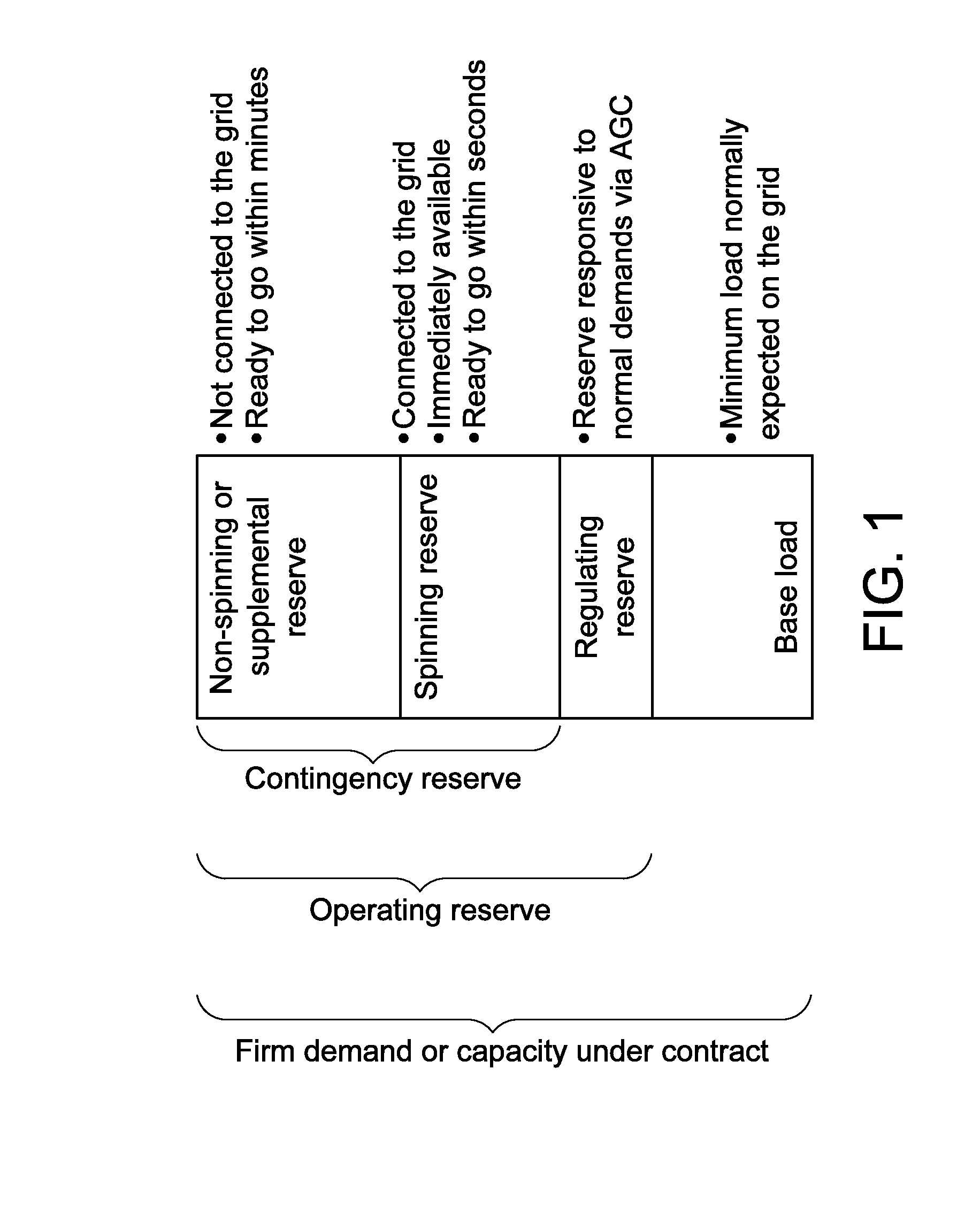
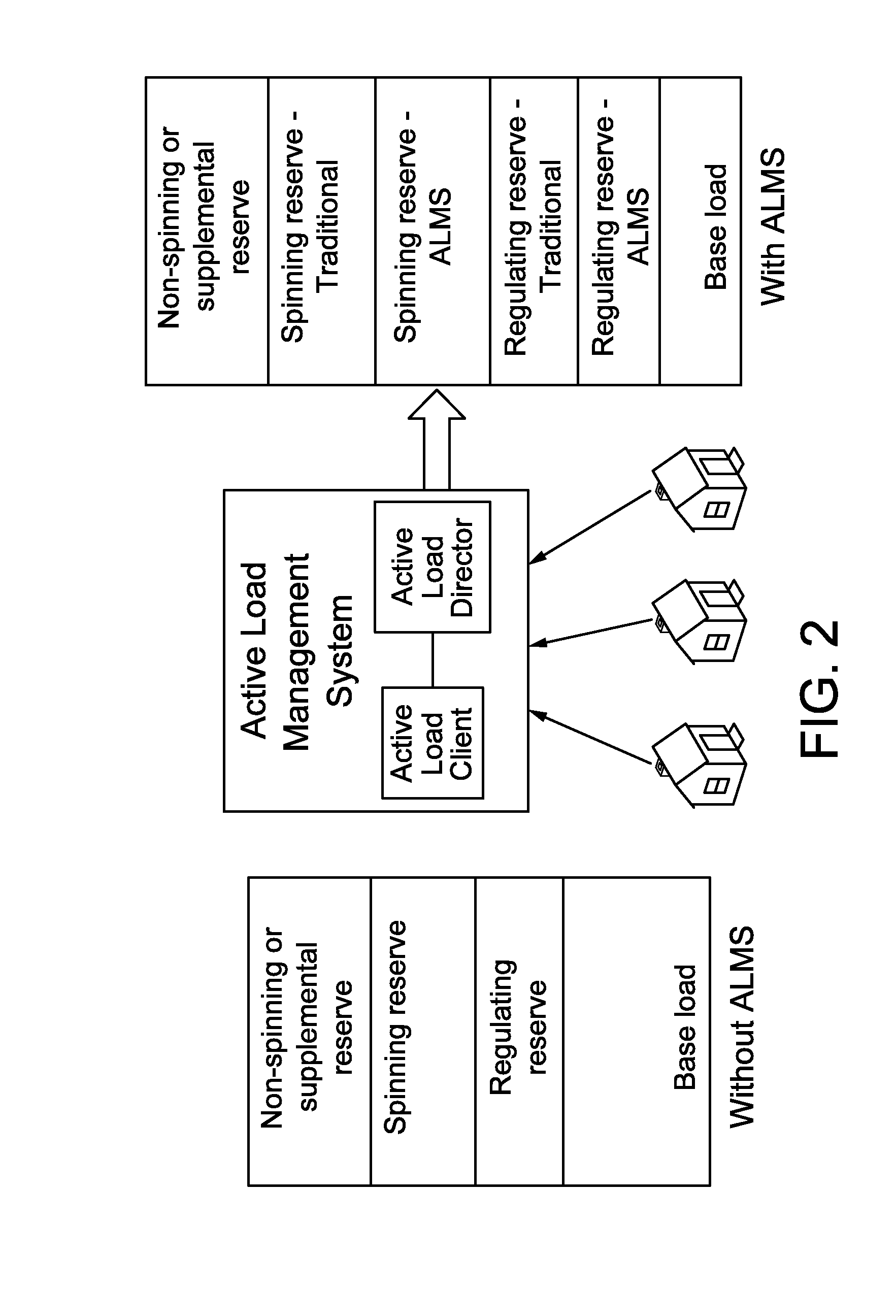
Typically, when additional power is needed for use as economic dispatch, a power utility will make use of its spinning reserve before using its non-spinning reserve because (a) the generation methods used to produce spinning reserve capacity typically tends to be cheaper than the methods, such as one-way traditional demand response, used to produce non-spinning reserve or (b) the consumer impact to produce non-spinning reserve is generally less desirable than the options used to produce spinning reserve due to other considerations, such as environmental concerns.
However, making use of either spinning reserve or non-spinning reserve results in additional costs to the utility because of the costs of fuel, incentives paid to consumers for traditional demand response, maintenance, and so forth.
When demand is greater than supply or capacity (i.e., the utility is under-generating or under-supplying), the quantity (NIA−NIS) is nega

Method used


Image

  • System and method for estimating and providing dispatchable operating reserve energy capacity through use of active load management
  • System and method for estimating and providing dispatchable operating reserve energy capacity through use of active load management
  • System and method for estimating and providing dispatchable operating reserve energy capacity through use of active load management

Examples


Embodiment Construction

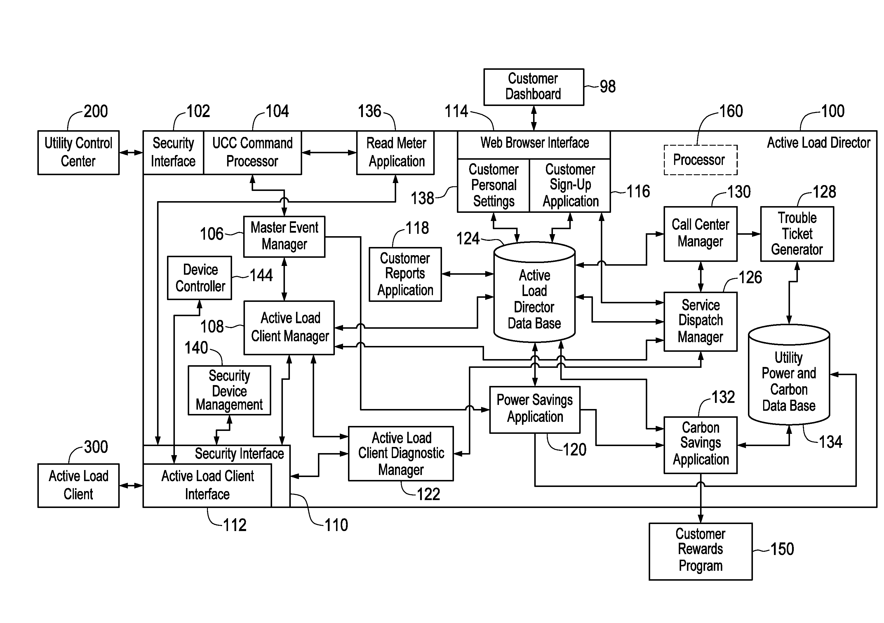
[0039]Before describing in detail exemplary embodiments that are in accordance with the present invention, it should be observed that the embodiments reside primarily in combinations of apparatus components and processing steps related to actively monitoring and managing power loading at an individual service point (e.g., on an individual subscriber basis) and throughout a utility's service area, as well as determining available or dispatchable operating reserve power derived from projected power savings resulting from monitoring and management of power loading. Accordingly, the apparatus and method components have been represented where appropriate by conventional symbols in the drawings, showing only those specific details that are pertinent to understanding the embodiments of the present invention so as not to obscure the disclosure with details that will be readily apparent to those of ordinary skill in the art having the benefit of the description herein.

[0040]In this document,...


PUM


Abstract

A utility employs a method for estimating available operating reserve. Electric power consumption by at least one device serviced by the utility is determined during at least one period of time to produce power consumption data. The power consumption data is stored in a repository. A determination is made that a control event is to occur during which power is to be reduced to one or more devices. Prior to the control event and under an assumption that it is not to occur, power consumption behavior expected of the device(s) is estimated for a time period during which the control event is expected to occur based on the stored power consumption data. Additionally, prior to the control event, projected energy savings resulting from the control event are determined based on the devices' estimated power consumption behavior. An amount of available operating reserve is determined based on the projected energy savings.

Description

CROSS REFERENCE TO RELATED APPLICATIONS[0001]This application is a continuation-in-part of U.S. application Ser. No. 11 / 895,909 filed on Aug. 28, 2007, now U.S. Pat. No. 7,715,951, which application is incorporated herein by this reference as if fully set forth herein. This application is also a continuation-in-part of co-pending U.S. application Ser. No. 12 / 001,819 filed on Dec. 13, 2007, which application is incorporated herein by this reference as if fully set forth herein. This application further claims priority under 35 U.S.C. §119(e) upon U.S. Provisional Application Ser. No. 61 / 215,725 filed on May 8, 2009 solely to the extent of the subject matter disclosed in said provisional application, which application is incorporated herein by this reference as if fully set forth herein.BACKGROUND OF THE INVENTION[0002]1. Field of the Invention[0003]The present invention relates generally to the field of electric power supply and generation systems and, more particularly, to a system ...

Claims


Application Information

Patent Timeline
IPC IPC(8): G06F1/32G06F1/28
CPCG06Q10/00H02J3/14H02J2003/003Y02B70/3225Y02E40/76G05B13/02G06Q50/06Y04S10/54Y04S10/545Y04S20/222H02J3/003H02J3/004H02J2310/60H02J3/144Y02B90/20Y04S20/00H02J3/12Y02E40/70Y04S10/50
Inventor FORBES, JR., JOSEPH W.WEBB, JOEL L.
Owner LANDISGYR INNOVATIONS INC
Why Eureka
Try Eureka