
Method for adapting the output of a steam-turbine power station, and steam-turbine power station

a technology of power station and output, which is applied in the direction of steam engine plants, machines/engines, ac network load balancing, etc., can solve the problems of small braking of generators, rate drop, network frequency drop, etc., and achieve the effect of increasing the overall efficiency of the power plant process

Active Publication Date: 2021-03-09
CARBON CLEAN TECH GMBH
View PDF22 Cites 0 Cited by
  • Summary
  • Abstract
  • Description
  • Claims
  • Application Information

AI Technical Summary

Benefits of technology

The patent describes a system for generating power using a hot air flow. The system includes an accumulator that can be emptied by passing air through the hot material. The hot air flow can be expanded and used to preheat the feed water before it is heated in a power plant. This allows for more flexible adjustment of power output to meet different power demands, and increases the overall efficiency of the power plant process.

Problems solved by technology

If the grid load, that is to say the total power consumption in a interconnected grid, increases in an unpredictable manner, that is to say the instantaneously fed-in power of all power stations increases, this leads to a slight braking of the generators and thus to a decrease in the network frequency.
The same occurs if the feed rate decreases unexpectedly, for example due to the failure of a power plant.
Due to the restricted volumes of these condensate reservoirs, however, the condensate accumulation is limited to a few minutes.
In this way, the multiple output of the power plant, which can be made available for a short time by the condensate accumulation, is limited by the maximum steam generator output, since the steam generator has to remove the condensate build-up in a short time.
The accumulation of condensate and the known throttling method result in the operation of the power plant with reduced efficiency.
During a minimum load operation of the power plant, it is then usually not possible in conventional power plant concepts to provide negative control power.
The energizing of the thermal accumulator with electrical energy generated by the power plant leads to a reduction of the effective power or current feed into the power grid.

Method used


Image

  • Method for adapting the output of a steam-turbine power station, and steam-turbine power station
  • Method for adapting the output of a steam-turbine power station, and steam-turbine power station
  • Method for adapting the output of a steam-turbine power station, and steam-turbine power station

Examples


Embodiment Construction

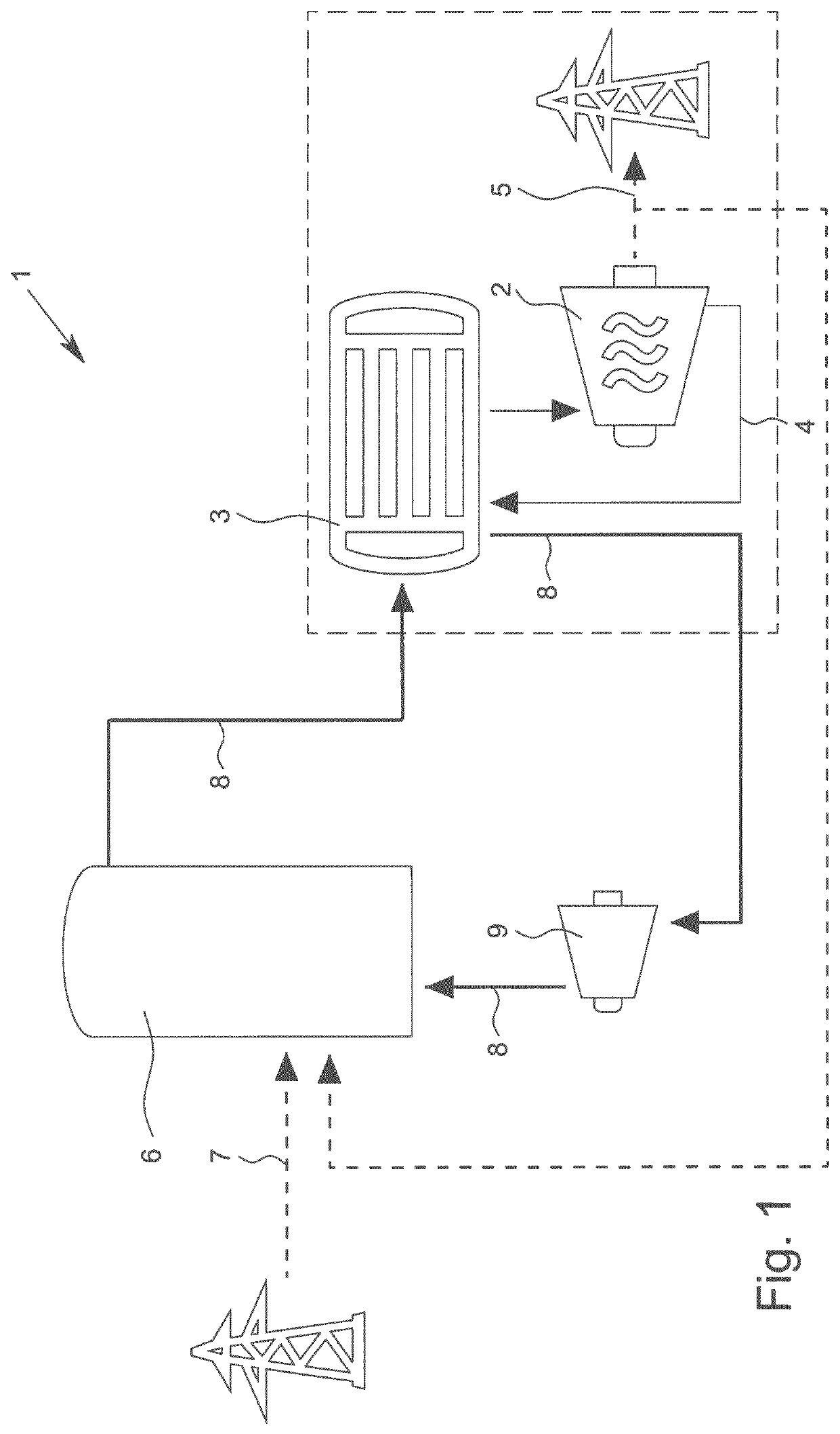
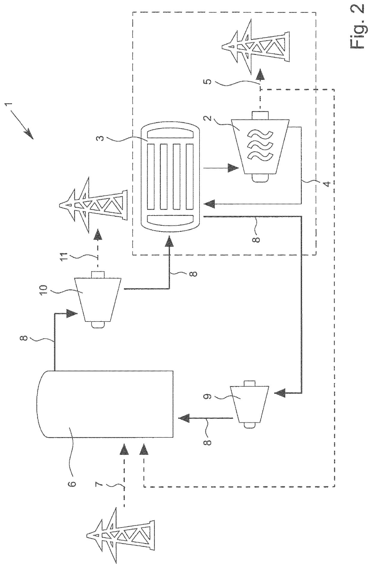
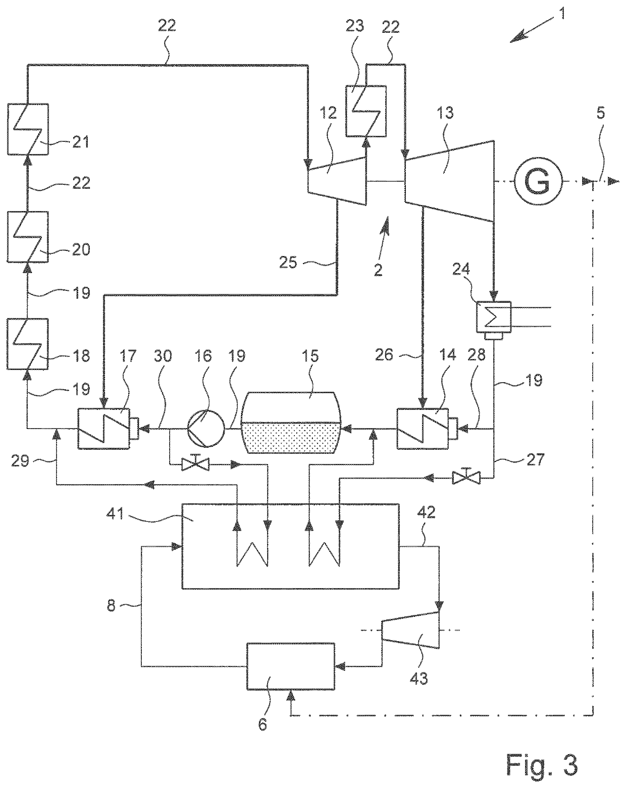
[0046]FIG. 1 shows a simplified plant diagram of a steam turbine power plant 1 with a schematically represented steam turbine 2, which can have a high-pressure part, a medium-pressure part and a low-pressure part. Furthermore, a feed water preheating section 3 of a water-steam working circuit 4 is shown schematically, in which feed water for the subsequent evaporation is preheated. The electrical net power or active power 5 generated in the power plant process is fed into an interconnected power grid. Further plant components required for generating power in the steam power process are not shown in FIG. 1.

[0047]For rapid and flexible adaptation of the effective power 5 of the power plant 1, further preferably for providing positive and negative grid control power, if necessary, at least one electrically loadable thermal accumulator is provided. In order to charge the accumulator 6, electrical power 7 can be removed from the interconnected power grid 7 and / or a part of the electrical...


PUM


Abstract

Disclosed is a method for rapidly and flexibly adapting the output of a steam-turbine power station (1), preferably for adapting the output to altered network loads, more preferably for providing a positive and / or negative network operating reserve as required, and especially preferably for providing a primary operating reserve and / or a secondary operating reserve. According to the invention, heat released during the discharge of at least one electrically chargeable thermal store (6) is coupled into a feedwater heater section (3) of the power station (1).

Description

[0001]This application is the National Phase of PCT Application No. PCT / EP2017 / 025177, filed Jun. 21, 2017, which claims the benefit of German Patent Application Serial No. 102016008520.7, filed Jul. 15, 2016, and European Patent Application Serial Nos. 16020391.5 and 16020509.2, filed Oct. 10, 2016 and Dec. 22, 2016, respectively, the entire disclosures of which are incorporated by reference herein.FIELD OF THE INVENTION[0002]The invention relates to a method for rapidly and flexibly adapting the output of a steam turbine power plant, preferably for output adaptation to changed network loads, further preferably for providing control power output depending on demand, particularly preferably for providing primary and / or secondary control power output. The invention further relates to a steam turbine power plant comprising at least one steam turbine and further required plant components for the power plant process, such as feed water preheaters, evaporators, steam superheaters, pump a...

Claims


Application Information

Patent Timeline
Patent Type & Authority Patents(United States)
IPC IPC(8): F01K13/02F01K3/06F01K7/44H02J3/28
CPCF01K13/02F01K3/06F01K7/44H02J3/28
Inventor PFAB, ROBERT JOSEPHZOELLNER, LARSKNOP, KLAUS
Owner CARBON CLEAN TECH GMBH
Learn More