Electric vehicles operation management equipment

A technology for electric vehicles and charging facilities, applied in electric vehicles, electric vehicle charging technology, motor vehicles, etc., can solve problems such as increasing the total operating value of EVs

Pending Publication Date: 2020-08-21
HITACHI LTD
View PDF5 Cites 0 Cited by
  • Summary
  • Abstract
  • Description
  • Claims
  • Application Information

AI Technical Summary

Problems solved by technology

Implementation of such related technologies may miss the opportunity to increase the total operating value of the EV

Method used


Image

  • Electric vehicles operation management equipment
  • Electric vehicles operation management equipment
  • Electric vehicles operation management equipment

Examples


Embodiment Construction

[0028]The following detailed description provides further details of the drawings and example embodiments of the present application. Reference numerals and descriptions of redundant elements between drawings are omitted for clarity. The terms used throughout the specification are provided by way of example only and are not intended to be limiting. For example, use of the term "automatic" can refer to fully automatic implementations or semi-automatic implementations, depending on the desired implementation by those of ordinary skill in the art practicing embodiments of the present application, with semi-automatic implementations involving user or administrator control of the implementation certain aspects of the control. Selection may be made by the user through a user interface or other input means, or may be accomplished by a desired algorithm. The example embodiments described herein can be used alone or in combination, and the functions of the example embodiments can be ...


PUM


Abstract

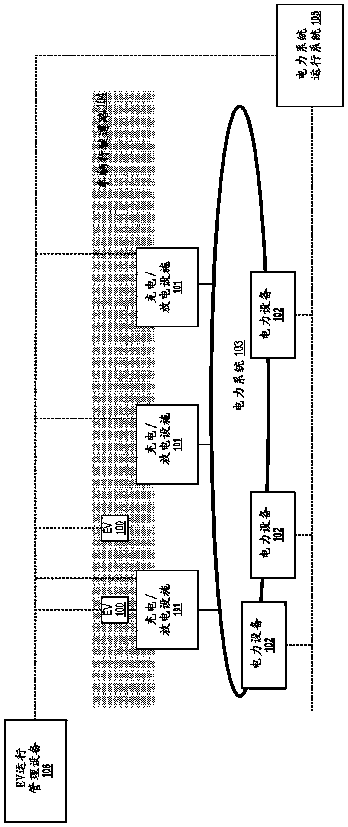
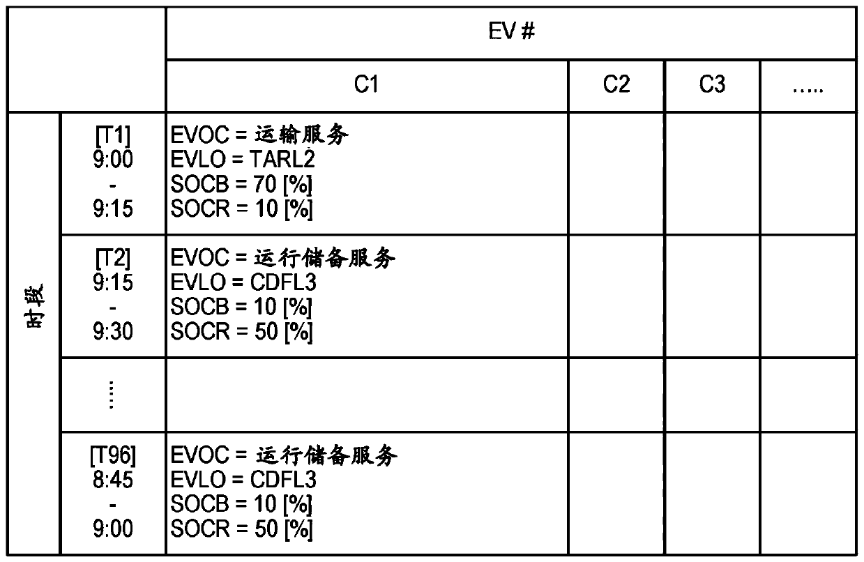
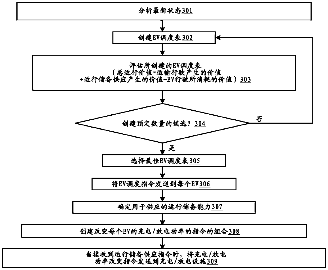
Example implementations described herein are directed to managing the operation of a plurality of electric vehicles (EVs) for transportation service, power system operating reserve service (ORS) and operation planning, which is utilized to determine whether to use each EV 100 for transportation travel or power system operating reserve supply for a given time period and location. Such management allows for the increase of the total operation value by transportation travel and power system operation reserve supply.

Description

technical field [0001] The present disclosure relates generally to electric vehicles, and more particularly to management equipment for power systems and operation of electric vehicles. Background technique [0002] In order for a power system to operate, there may be a need to maintain a balance between the supply and demand of electricity. However, end-user electricity consumption and electricity generation from renewable sources fluctuate independently and lead to uncertainty. For the power system to operate stably, this gap may need to be filled by regulating generation and demand at any given time. [0003] In the system of the related art, the amount of power generation is adjusted by controlling a thermal power plant and the amount of demand is adjusted by adjusting the amount of use of electrical equipment. This related art method of adjusting the gap between supply and demand is called "power system operating reserve" (hereinafter referred to as "operating reserve...

Claims


Application Information

Patent Timeline
Patent Type & Authority Applications(China)
IPC IPC(8): G06Q10/06G06Q50/06G06Q50/30
CPCG06Q10/0631G06Q10/06315G06Q50/06G06Q50/30H02J3/322B60L53/66B60L53/67B60L53/68B60L53/63Y02T10/70Y02T10/7072Y02T90/12Y02T90/16Y04S10/126Y02E60/00B60Y2200/91
Inventor 富田泰志杨博帕尼塔恩·庄方宾耶叶艳珠
Owner HITACHI LTD
Why Eureka
Try Eureka