Low voltage compressor operation for a fuel cell power system

a fuel cell power system and compressor technology, applied in the direction of positive displacement liquid engine, cell components, pump, etc., can solve the problems of insufficient power in the fuel cell stack, inability to power the airmover, and addition of extra components to the system

Inactive Publication Date: 2006-04-20
GM GLOBAL TECH OPERATIONS LLC
View PDF2 Cites 22 Cited by
  • Summary
  • Abstract
  • Description
  • Claims
  • Application Information

AI Technical Summary

Benefits of technology

[0007] The present invention provides an apparatus and method for starting up a fuel cell power system utilizing a low voltage power source to drive the airmover power control system which powers the airmover. The apparatus and method may also be used to switch operation of the fuel cell power system between using the low voltage power source and stack power to drive the airmover power control system and power the airmover. A fuel cell system according to the principles of the present invention include a fuel cell stack operable to produce electrical power using an anode reactant and a cathode reactant. There is an airmover that is operable to supply the cathode reactant to the fuel cell stack. There is also a low voltage power source which is operable to supply low voltage power. A controller system selectively powers the airmover using the low voltage power source and the power produced by the fuel cell stack. The controller system is operable to power the airmover at system idle with a same voltage and current value regardless of using the low voltage power and the stack power.

Problems solved by technology

During start-up of the fuel cell system, however, the fuel cell stack is not producing enough power and is unavailable to power the airmover.
Furthermore, during a shutdown operation it may be desired to perform a purging operation using the airmover while the fuel cell stack is not producing sufficient power to power the airmover.
These methods, however, have proven to be complex and / or result in the addition of extra components to the system that can add weight and / or take up valuable space.

Method used


Image

  • Low voltage compressor operation for a fuel cell power system
  • Low voltage compressor operation for a fuel cell power system
  • Low voltage compressor operation for a fuel cell power system

Examples


Embodiment Construction

[0014] The following description of the preferred embodiment is merely exemplary in nature and is in no way intended to limit the invention, its application, or uses. As used herein, the term module refers to an application specific integrated circuit (ASIC), an electronic circuit, a processor (shared, dedicated or group) and memory that execute one or more software or firmware programs, a combinational logic circuit, or other suitable components that provide the described functionality.

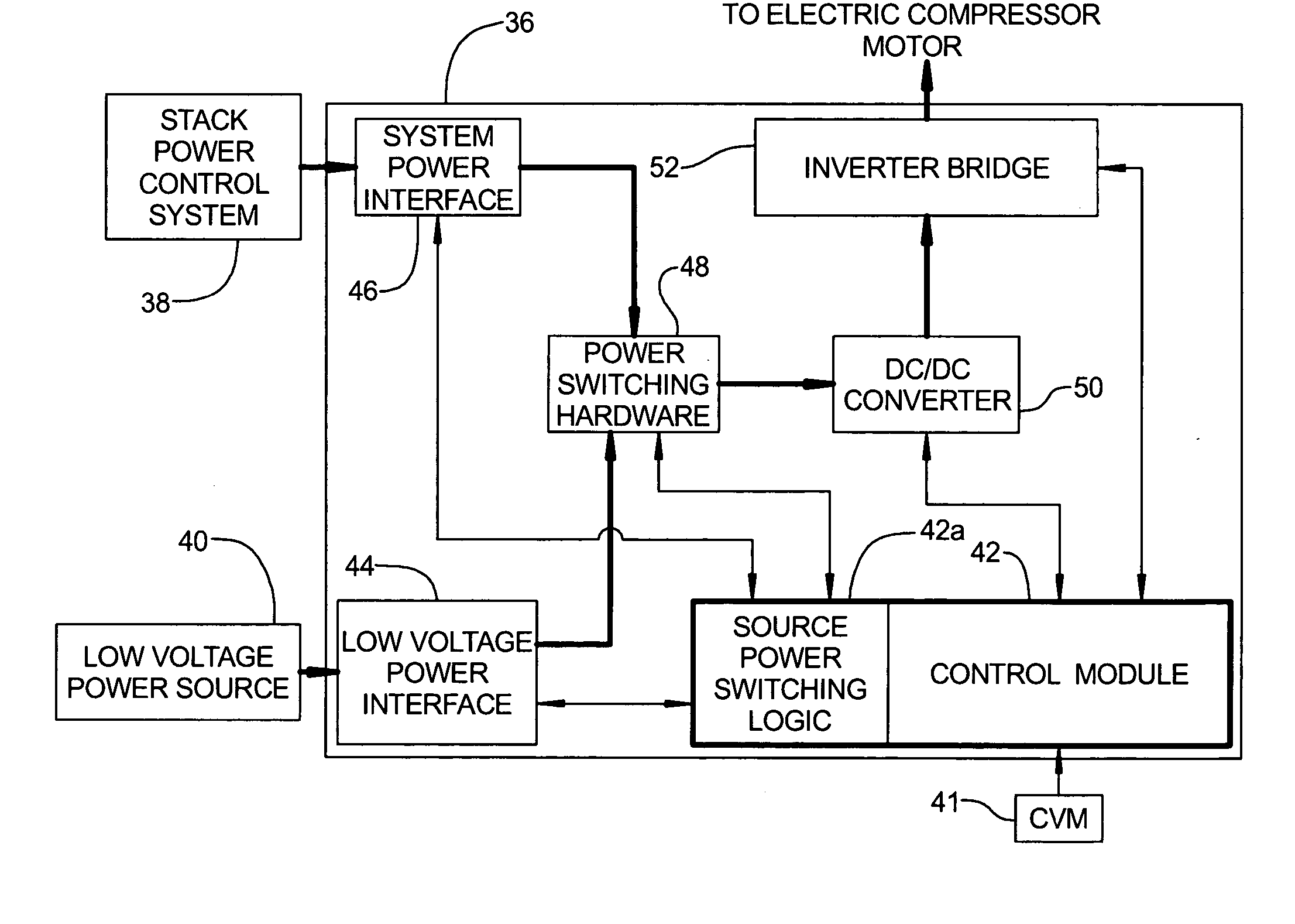
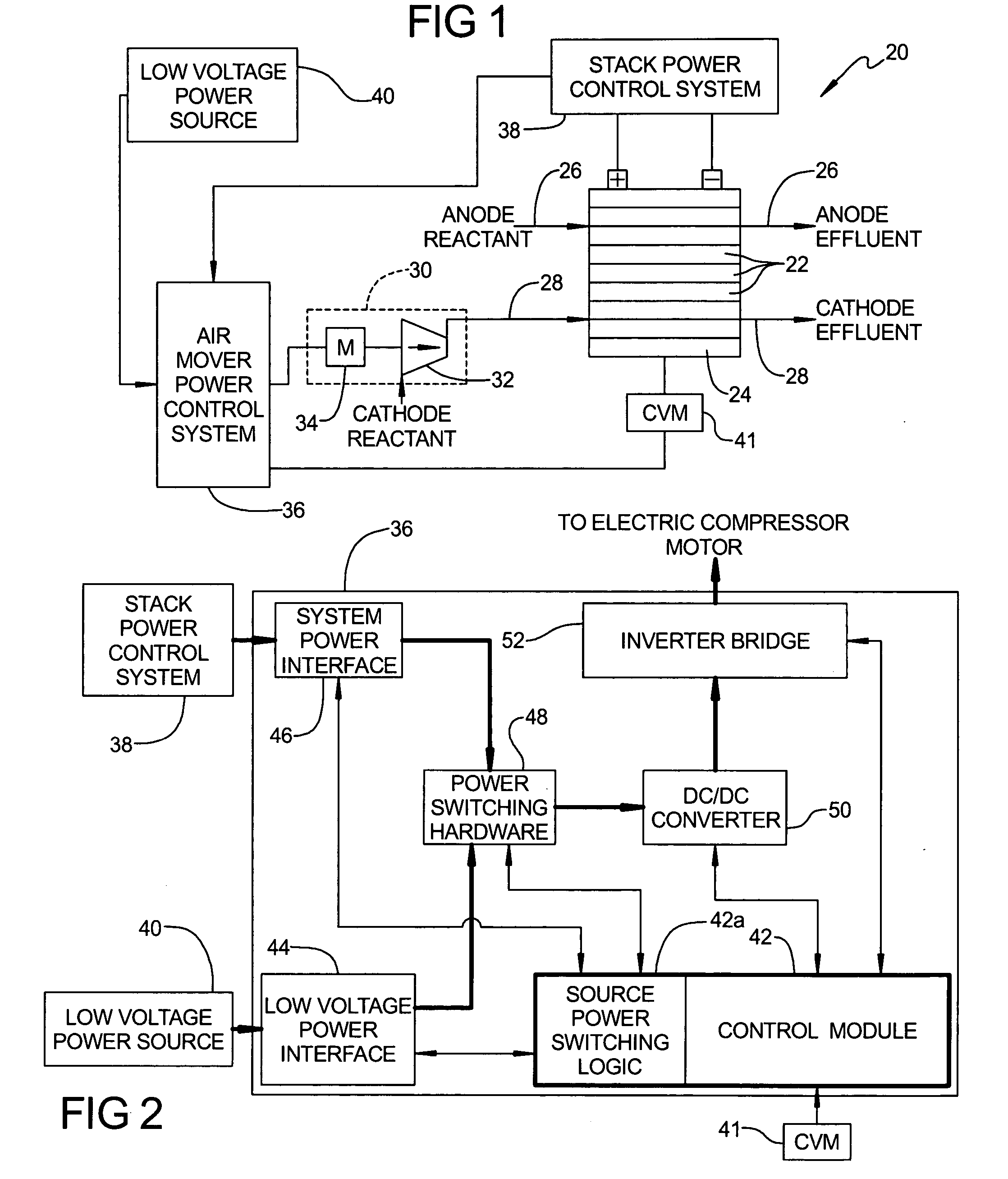
[0015] Referring now to FIG. 1, a fuel cell system 20 according to the principles of the present invention is shown. Fuel cell system 20 includes a plurality of fuel cells 22 arranged in a stacked configuration to form a fuel cell stack 24. Fuel cell stack 24 has an anode reactant flow path 26 and a cathode reactant flow path 28 that are used to provide the respective anode and cathode reactants to fuel cell stack 24. Each flow path 26, 28 includes the internal flow paths within each fuel cell 22 wi...


PUM

PropertyMeasurementUnit
voltageaaaaaaaaaa
voltageaaaaaaaaaa
frequencyaaaaaaaaaa

Abstract

An apparatus and method for operating a fuel cell power system utilizing a low voltage power source and system power to power an airmover. The fuel cell power system uses a low voltage power source to power the airmover during start-up and transitions to using system power to power the airmover as the fuel cell stack increases its voltage output. During a shutdown operation the fuel cell power system transitions from using system power to using the low voltage power source to power the airmover enabling a purging operation to be performed. A controller coordinates the operation of the airmover between using the low voltage power source and using electrical power produced by the fuel cell stack to power the airmover.

Description

FIELD OF THE INVENTION [0001] The present invention relates to fuel cell power systems and, more particularly, to low voltage compressor start for a fuel cell power system. BACKGROUND OF THE INVENTION [0002] Fuel cells can be used as a power source in many applications. For example, fuel cells can be used in electrical vehicular power plants to replace internal combustion engines and in stationary applications to produce electrical power. In proton exchange membrane (PEM) type fuel cells, hydrogen is supplied to the anode of the fuel cell and oxygen is supplied to the cathode. PEM fuel cells include a membrane electrode assembly (MEA) comprising a thin, proton transmissive, non-electrically conductive solid polymer electrolyte membrane having the anode catalyst on one of its faces and the cathode catalyst on the opposite face. The MEA is sandwiched between a pair of electrically conductive elements that serve as current collectors for the anode and cathode. The conductive elements c...

Claims


Application Information

Patent Timeline
Patent Type & Authority Applications(United States)
IPC IPC(8): H01M8/04
CPCF04B35/04H01M8/04089H01M8/04223H01M8/04231H01M8/04552H01M8/04559H01M8/04619H01M8/04753H01M8/04955H01M8/04992H01M16/006Y02E60/50H01M8/241H01M8/04225H01M8/04228H01M8/04302H01M8/04303H01M8/2457Y02E60/10
Inventor RAINVILLE, JOSEPH D.BONKOSKE, JOHN R.LOGAN, VICTOR W.
Owner GM GLOBAL TECH OPERATIONS LLC
Why Eureka
Try Eureka