Air Delivery Conduit

a technology of air delivery and conduits, applied in the field of respiratory therapy, can solve the problems of air temperature rise, plastics and metals are not efficient thermal insulation agents, and the condensation problem is particularly severe, and achieve the effect of light weight and better insulating properties

Active Publication Date: 2010-09-09
RESMED LTD +2
View PDF22 Cites 37 Cited by
  • Summary
  • Abstract
  • Description
  • Claims
  • Application Information

AI Technical Summary

Benefits of technology

[0014]Another aspect of the invention relates to an air delivery conduit for conveying breathable gas from a positive airway pressure device to a patient interface. The air delivery conduit includes a tubular wall structure constructed from a textile material and a reinforcing structure provided to the wall structure. The reinforcing structure is structured to prevent kinking or collapsing of the wall structure.
[0016]Advantageously, textiles (including woven and non-woven textiles) usually provide better insulating properties than plastics and are often lighter in weight. A non-porous textile advantageously prevents breathing gas escaping from the conduit (and the resultant pressure losses).

Problems solved by technology

The condensation problem is particularly pronounced in cold environments.
Plastics and metals are not efficient thermal insulators.
Actively heating the tube may result in the air temperature rising as it travels along the tube which in turn will result in the air drying out.
Present conduits can also be heavy causing an uncomfortable resistance to patient head movements.
Additional items, such as an insulating sleeve, added to the conduit may cause the overall weight to increase.

Method used


Image

  • Air Delivery Conduit
  • Air Delivery Conduit
  • Air Delivery Conduit

Examples


Embodiment Construction

2.1 Structure

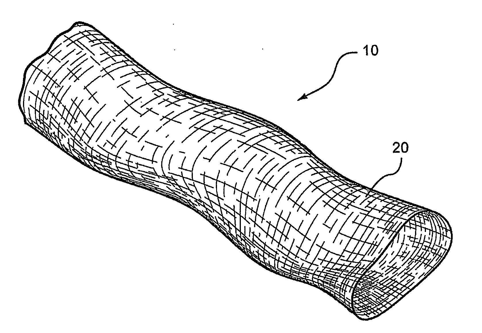
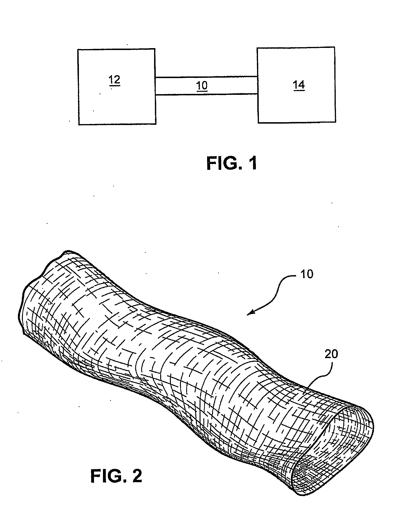
[0023]As schematically shown in FIG. 1, an air delivery conduit 10 is provided that is suitable to deliver air from a positive airway pressure device (PAP device), blower, flow generator, or ventilator 12 to a patient interface 14 to provide respiratory therapy. In one form the conduit 10 is at least partly constructed from a textile.

[0024]For example, FIG. 2 illustrates a conduit 10 according to an embodiment of the present invention. As illustrated, a wall or wall structure 20 of the conduit 10 is at least partly constructed from a textile. The conduit 20 may be provided with suitable end portions, e.g., plastic cuffs, that are structured to connect the conduit 10 to each of the PAP device 12 and the patient interface 14.

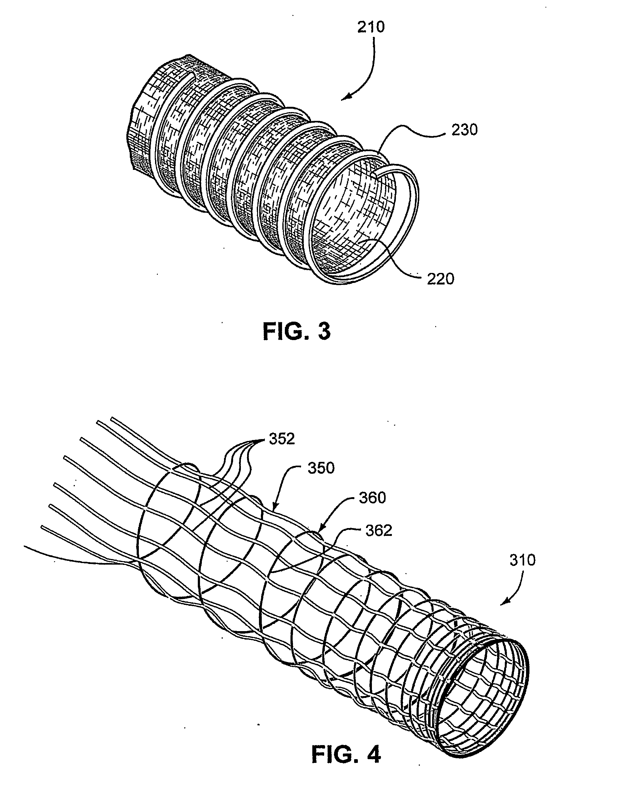
[0025]In one form, the conduit includes a reinforcing structure and a wall structure, and at least a portion of either the reinforcing structure or the wall structure includes a textile. For example, FIG. 3 illustrates a conduit 210 according to anoth...


PUM


Abstract

An air delivery conduit for conveying breathable gas from a positive airway pressure device to a patient interface includes a tubular wall structure constructed from a textile material. A reinforcing structure may be provided to the wall structure that is structured to prevent kinking or collapsing of the wall structure. The wall structure may include a warp having a plurality of lengthwise textile warp threads arranged in a circle and a weft having a textile weft thread that is woven through the warp threads.

Description

CROSS REFERENCE TO RELATED APPLICATIONS[0001]This application claims the benefit of Australian Provisional Application No. 2006901506, filed Mar. 24, 2006, which is incorporated herein by reference in its entirety.FIELD OF THE INVENTION[0002]The present invention relates generally to the field of respiratory therapy. More particularly, the invention relates to positive airway pressure devices (PAP devices), respirators, ventilators, CPAP or VPAP devices and conduits that form a component of such devices, the conduits being used for conveying breathing gas from the device to a patient interface.BACKGROUND1.0 Introduction[0003]Respiratory devices typically include a flexible conduit to convey a breathing gas such as air to a patient. Generally, the conduit should be strong enough to prevent crushing or kinking, as such could cause occlusions in the conduit thereby restricting or blocking the delivery of breathing gas.1.1 General Structure[0004]One known conduit structure includes a ha...

Claims


Application Information

Patent Timeline
Patent Type & Authority Applications(United States)
IPC IPC(8): A61M16/08A61M16/06D03D37/00
CPCA61M16/142A61M16/08A61M16/0875A61M2205/02A61M2207/00A61M16/0057
Inventor HENRY, ROBERT EDWARD
Owner RESMED LTD
Why Eureka
Try Eureka