Inserter Having Two Springs

Active Publication Date: 2010-09-09
UNOMEDICAL AS
View PDF98 Cites 107 Cited by
  • Summary
  • Abstract
  • Description
  • Claims
  • Application Information

AI Technical Summary

Problems solved by technology

This insertion device is rather complex and the length of the device is defined by the individual units forming the functional parts of the device as these units have to be placed more or less end to end.
A feature illustrating the complexity of the unit

Method used


Image

  • Inserter Having Two Springs
  • Inserter Having Two Springs
  • Inserter Having Two Springs

Examples


Embodiment Construction

[0005]The object of the invention is to provide a simple, non-expensive inserter for an infusion device which inserter would be easy and safe for the user to handle during use and safe to dispose of after use.

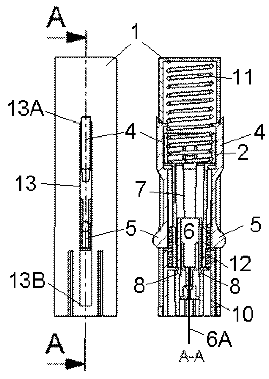
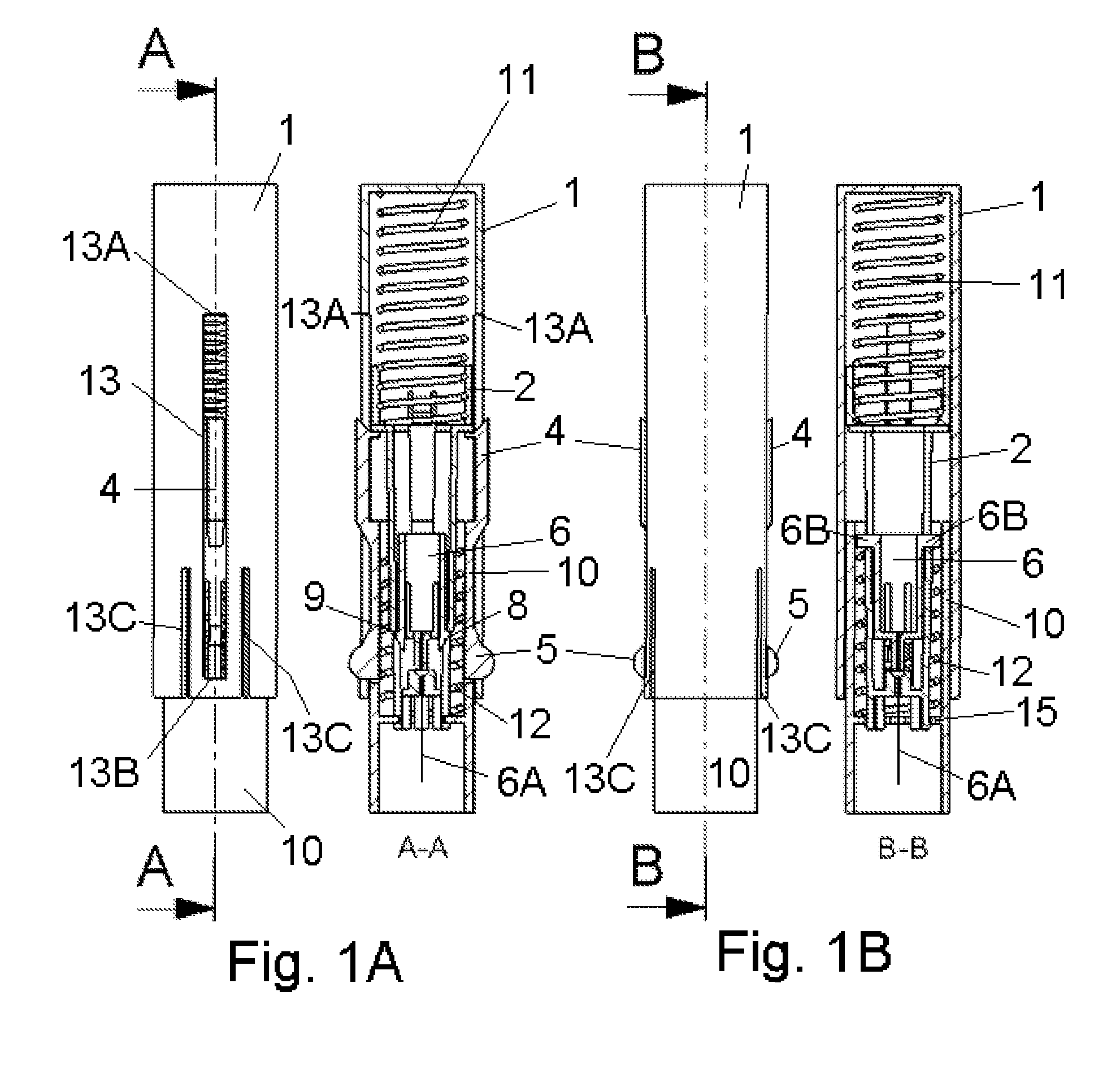
[0006]The invention concerns an inserter for a medical device comprising two elastic elements where activation of the first elastic element cause a penetrating member to be inserted sub- or transcutaneously into the skin of a patient, and the second elastic element cause the penetrating member to be retracted from the skin of the patient wherein the first elastic element is in an unloaded state before activation and upon activation the first elastic element energizes the second elastic element. That the first elastic element is in an unloaded state means that it is un-biased or slightly biased, and only upon activation the first elastic element will be loaded. This assures that the first elastic element does not decay during storing before use.

[0007]According to this invention ...


PUM


Abstract

The invention relates to an inserter for a medical device e.g. an infusion set or the like for intermittent or continuous administration of a therapeutical substance, such as e.g. insulin. The inserter comprises a needle hub comprising an insertion needle and two elastic elements assuring automatic insertion and automatic retraction of the insertion needle. Activation of the first elastic element (11) cause a penetrating member (6A) to be inserted sub-or transcutaneously into the skin of a patient, and the second elastic element (12) cause the penetrating member (6A) to be retracted from the skin of the patient. The first elastic element (11) is in an unloaded state before activation and upon activation the first elastic element (11) energizes the second elastic element (12).

Description

TECHNICAL FIELD[0001]The invention relates to an inserter for a medical device e.g. an infusion set or the like for intermittent or continuous administration of a therapeutical substance, such as e.g. insulin. The inserter comprises a needle hub comprising an insertion needle and two elastic elements assuring automatic insertion and automatic retraction of the insertion needle.BACKGROUND OF THE INVENTION[0002]WO 2005 / 046780 (FIGS. 97-102) describes a device used for automatic insertion of a cannula of an infusion device into the skin of a patient, and afterwards automatic retraction of the insertion needle. The insertion device has the form of an oblong cylinder which is open in one end (1984) and provided with means for activation at the other end (1952). When the infusion set has been loaded onto the needle (1968) the lock member (1962) is moved in direction of the end provided with means for activation by the patient using projections (1974) until barbs (1956) of the lock member ...

Claims


Application Information

Patent Timeline
IPC IPC(8): A61M5/20
CPCA61B5/14532A61M5/158A61M2005/2013A61M2005/1581A61M2005/1585A61M5/3287
Inventor NIELSEN, JENS EGEBJERG
Owner UNOMEDICAL AS
Why Eureka
Try Eureka