
Circuit for controlling dynamic rotation speed of fan, method of controlling dynamic rotation speed of fan, and program for controlling dynamic rotation speed of fan

a technology of dynamic rotation speed and fan, which is applied in the direction of process and machine control, electrical apparatus casing/cabinet/drawer, instruments, etc., can solve the problems of unnecessarily loud noise, excessive fan rotation speed in low load state of computer, and noticeable temperature ris

Active Publication Date: 2010-09-09
NEC PLATFORMS LTD
View PDF8 Cites 26 Cited by
  • Summary
  • Abstract
  • Description
  • Claims
  • Application Information

AI Technical Summary

Benefits of technology

[0027]According to the present invention, in the control of a cooling fan provided in a computer, it is possible to prevent the fan from rotating at an excess speed in terms of cooling purpose while the computer is in a low load state, thereby reducing noise.

Problems solved by technology

In particular, due to recent advances in CPU performance, the temperature rise is noticeable.
However, a rotation of the cooling fan, which generates noise, is one of the major noise source of the computer such as server.
In general, the fan rotation speed is controlled taking the computer's peak load state into consideration, so that the fan rotation speed in the low load state of the computer is excessively high in terms of cooling purpose, and noise is unnecessarily loud.

Method used


Image

  • Circuit for controlling dynamic rotation speed of fan, method of controlling dynamic rotation speed of fan, and program for controlling dynamic rotation speed of fan
  • Circuit for controlling dynamic rotation speed of fan, method of controlling dynamic rotation speed of fan, and program for controlling dynamic rotation speed of fan
  • Circuit for controlling dynamic rotation speed of fan, method of controlling dynamic rotation speed of fan, and program for controlling dynamic rotation speed of fan

Examples


Embodiment Construction

[0033]An embodiment of the present invention will be described in detail below with reference to the accompanying drawings.

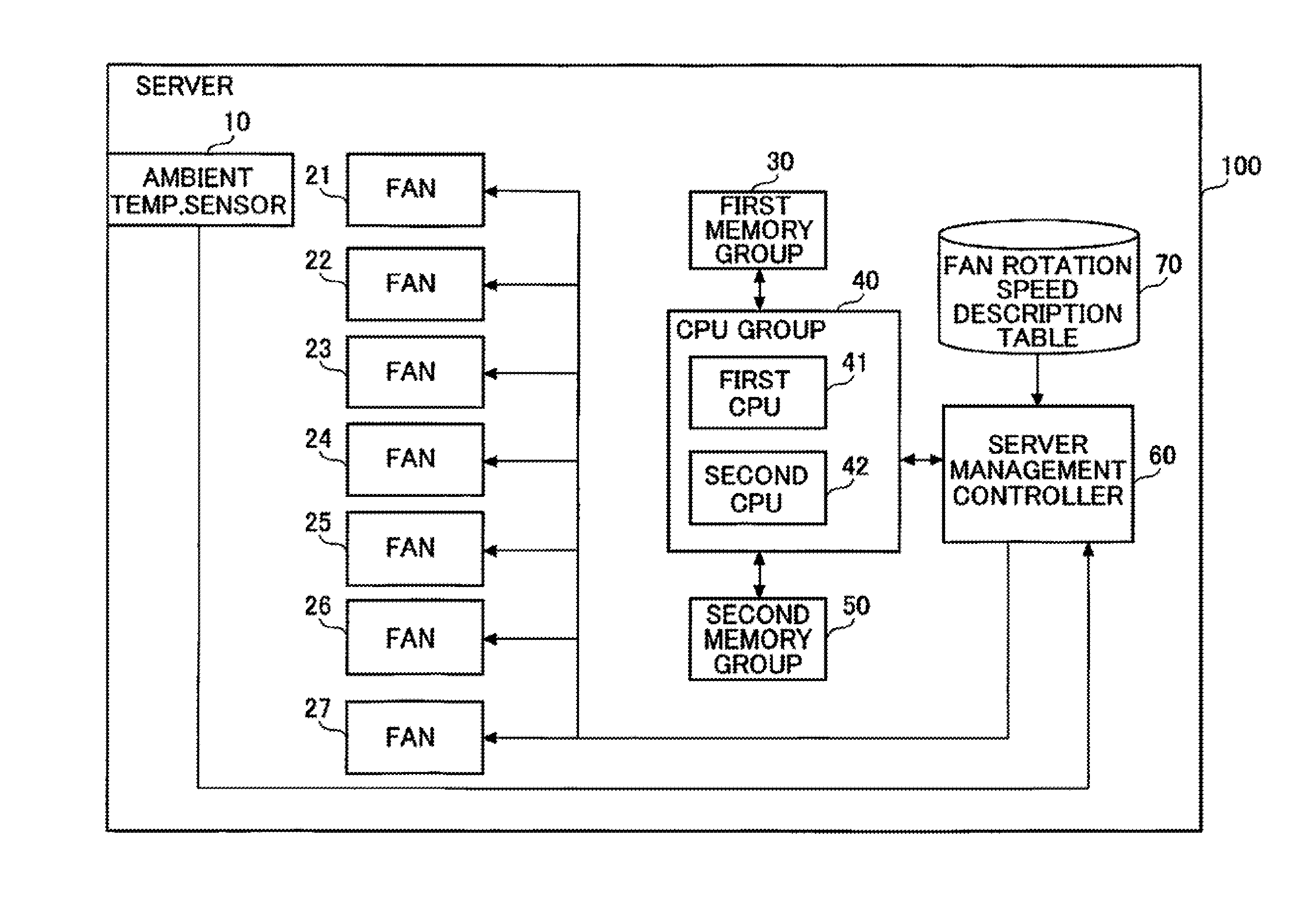
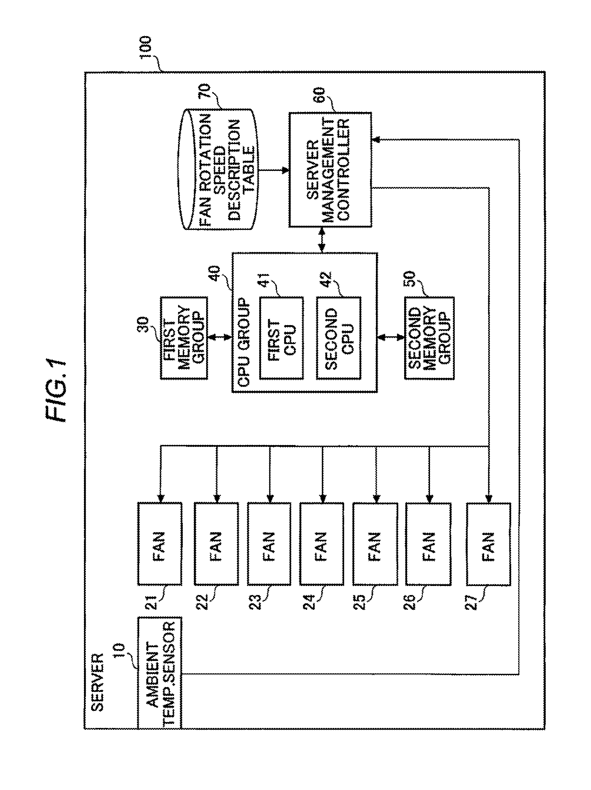
[0034]Referring to a block diagram of FIG. 1, a server 100 as a computer according to an embodiment of the present invention includes an ambient temperature sensor 10, fans 21 to 27, a first memory group 30, a CPU group 40, a second memory group 50, a server management controller 60, and a fan rotation speed description table 70. The CPU group 40 includes a first CPU 41 and a second CPU 42.

[0035]In the server 100, seven fans (fans 21 to 27) are used to cool the CPUs and memories, i.e. the first CPU 41 and the second CPU 42 in the CPU group 40, and the memories in the first memory group 30 and the second memory group 50. A temperature sensor (ambient temperature sensor 10) is installed at the front portion (on the suction side) of the server 100. CPUs (the first CPU 41 and the second CPU 42: up to two CPUs are supposed to be installed in the present embodiment) e...


PUM


Abstract

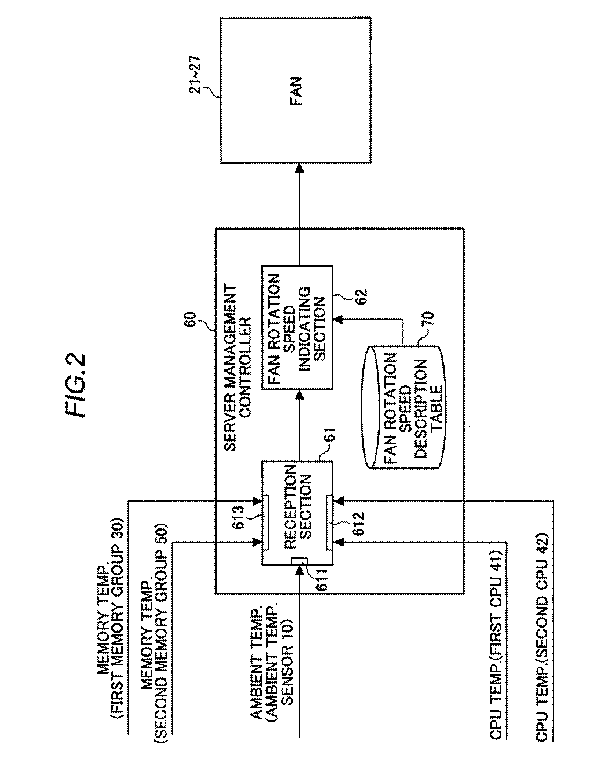
A first reception unit receives “ambient temperature” which is a temperature of surroundings where the computer is installed. A second reception unit receives “first device temperature” which is a temperature of a first device provided in the computer. A third reception unit receives “second device temperature” which is a temperature of a second device provided in the computer. A fan rotation speed indicating unit determines the rotation speed of the fan based on a comparison between the ambient temperature, first device temperature, and second device temperature which are received by the first to third reception units and a fan rotation speed description table describing a relationship between the respective temperature and fan rotation speed and instructs the fan to rotate at the determined rotation speed.

Description

TECHNICAL FIELD[0001]The present invention relates to control of the dynamic rotation speed of a cooling fan provided in a computer and, particularly to a circuit for controlling the dynamic rotation speed of fan, method of controlling the dynamic rotation speed of fan, and a program for controlling the dynamic rotation speed of fan.BACKGROUND ART[0002]In a computer, as typified by a server in a computer network system, etc., temperature rises as the operation of a CPU or a memory proceeds. In particular, due to recent advances in CPU performance, the temperature rise is noticeable. In order to prevent such a temperature rise, a method is generally employed in which a cooling fan is provided in the computer such as server, etc. so as to cool the inside of the computer.[0003]However, a rotation of the cooling fan, which generates noise, is one of the major noise source of the computer such as server. In general, the fan rotation speed is controlled taking the computer's peak load sta...

Claims


Application Information

Patent Timeline
Patent Type & Authority Applications(United States)
IPC IPC(8): G05D23/19
CPCG06F1/206G05D23/1931
Inventor ETO, JUN
Owner NEC PLATFORMS LTD
Learn More