Brow tool

a brow tool and brow technology, applied in the field of brow tools, can solve the problems of difficult to correct using cosmetics, difficult for a novice to style brows without assistance, semi-permanent cosmetic damage,

Active Publication Date: 2010-09-16
PLAIN NATALIE
View PDF15 Cites 8 Cited by
  • Summary
  • Abstract
  • Description
  • Claims
  • Application Information

AI Technical Summary

Problems solved by technology

Typically, it is difficult for a novice to style brows without assistance.
Because eye brows do not regrow easily, errors in brow styling can cause semi permanent cosmetic damage which is difficult to correct using cosmetics.

Method used


Image

  • Brow tool
  • Brow tool
  • Brow tool

Examples


Embodiment Construction

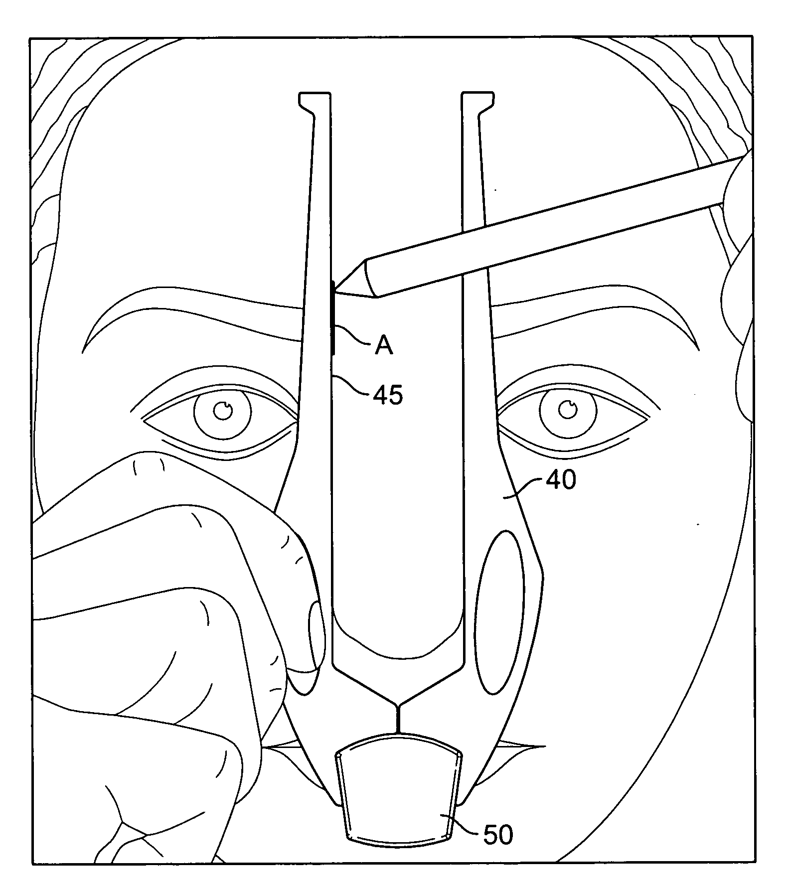
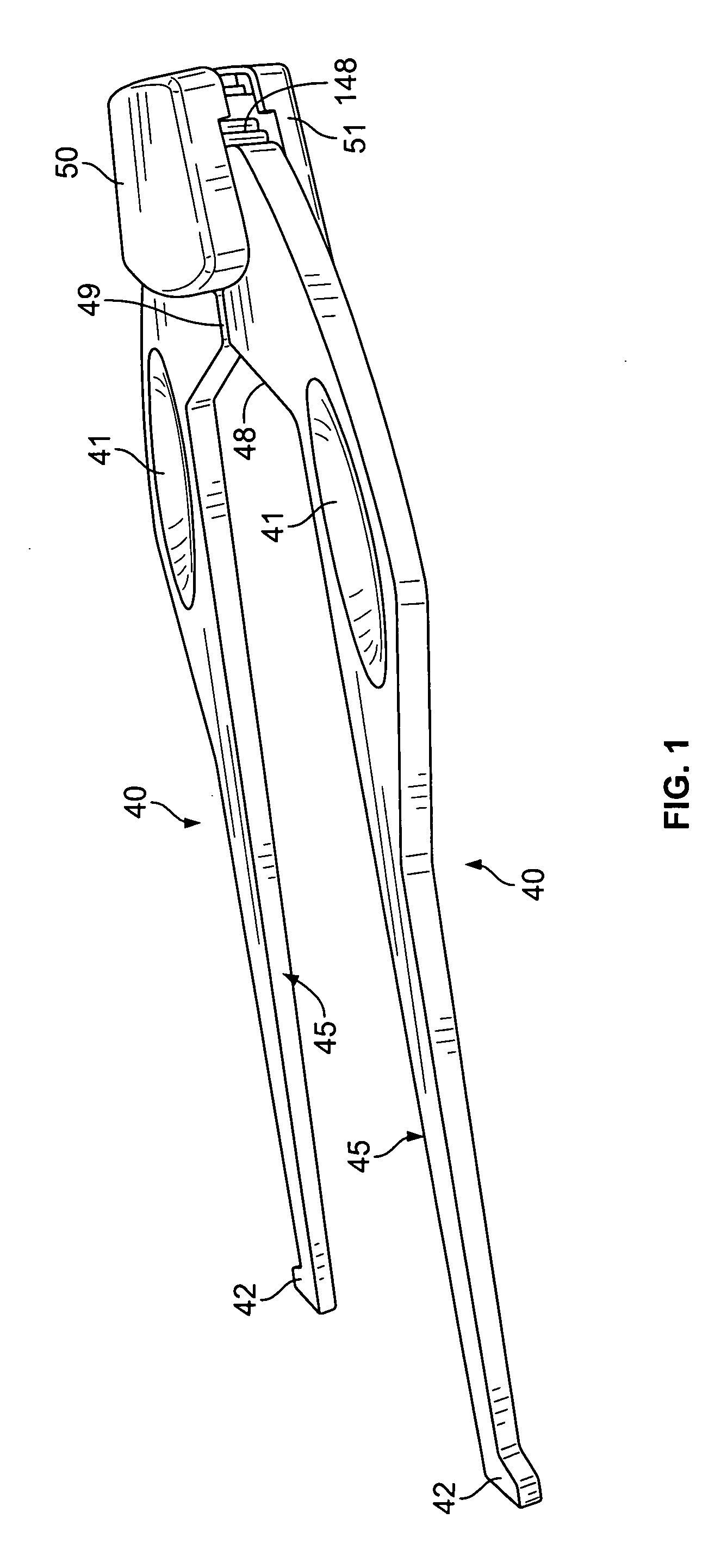
[0036]The present invention as seen in FIGS. 1-7, is a brow tool which has a variety of features for drawing brow defining lines. A user can use the brow tool for drawing brow defining lines to define an area in which to tweeze the eyebrows. The first extending arm and the second extending arm rotate relative to each other so that they can be rotated away from each other. The first extending arm and the second extending arm are adapted to angular extension from an initial 0° angle to a 180° angle.

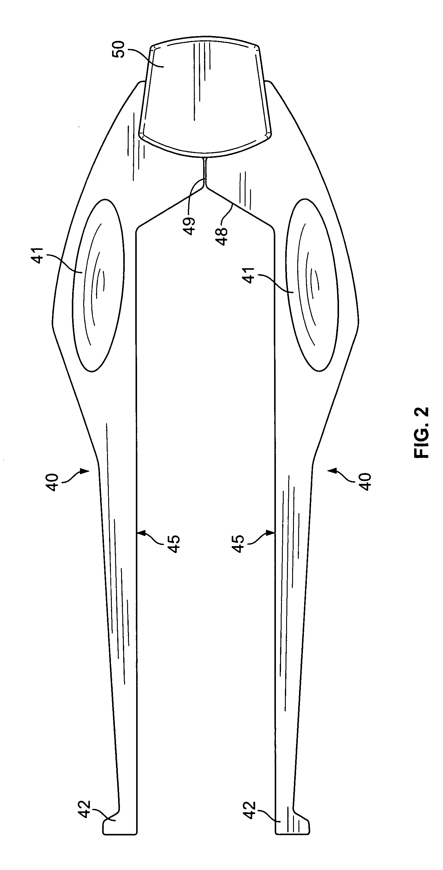
[0037]The brow tool in the best mode has a total of four parts. The first and second part are a pair of extending arms 40. Each extending arm 40 has a grip depression 41 disposed on a surface of the extending arm 40. The extending arm 40 also has an inside edge 45 and each inside straight edge 45 has a hook ending 42. The extending arms 40 have an inside angle 48 which is formed as an edge which joins the inside straight edge 45 to the abutting line 49. The abutting line 49 is comprised of ...


PUM


Abstract

A brow tool comprises a first extending arm. The first extending arm has a first gear at a base portion. A first straight edge is defined on an inside portion of the first extending arm. The first straight edge is offset in a latitudinal direction in the amount of one half of a gap distance, to provide a latitudinal offset. A second extending arm has a second gear at a base portion. A second straight edge is defined on an inside portion of the second extending arm. The second straight edge is offset in a latitudinal direction to provide a latitudinal offset in the amount of one half of a gap distance. A housing connects the first gear to the second gear so that the first gear is in meshed configuration with the second gear.

Description

[0001]This application is a continuation in part of and claims priority from design patent application filed entitled Brow Tool to same inventor Natalie Plain filed Mar. 10, 2009.DISCUSSION OF RELATED ART[0002]Brow styling is an ancient art requiring skill and patience. Typically, it is difficult for a novice to style brows without assistance. Because eye brows do not regrow easily, errors in brow styling can cause semi permanent cosmetic damage which is difficult to correct using cosmetics.SUMMARY OF THE INVENTION[0003]The present invention is a brow tool allowing a user to align and measure key metrics in brow styling. The present invention is an apparatus that has a bottom joint and a pair of extending arms extending from the bottom joint. The pair of extending arms have an inside edge spaced approximately 1 inch apart from each other. The pair of extending arms swivel relative to each other and provide a guide for defining a tweezing area.[0004]To use the invention, a user first...

Claims


Application Information

Patent Timeline
Patent Type & Authority Applications(United States)
IPC IPC(8): A45D40/30
CPCA45D40/30
Inventor PLAIN, NATALIE
Owner PLAIN NATALIE
Why Eureka
Try Eureka