Eureka AIR delivers breakthrough ideas for toughest innovation challenges, trusted by R&D personnel around the world.

Belt scraper tensioning assembly

Active Publication Date: 2010-09-16
SUPERIOR INDUSTRIES
View PDF13 Cites 6 Cited by
  • Summary
  • Abstract
  • Description
  • Claims
  • Application Information

AI Technical Summary

Benefits of technology

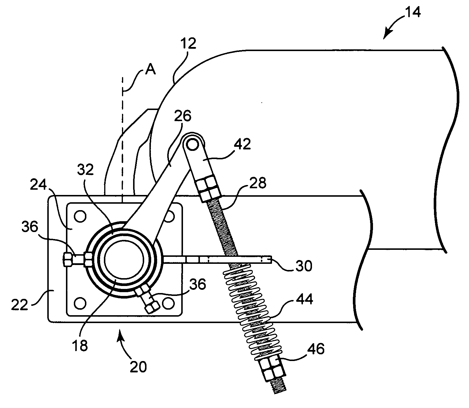
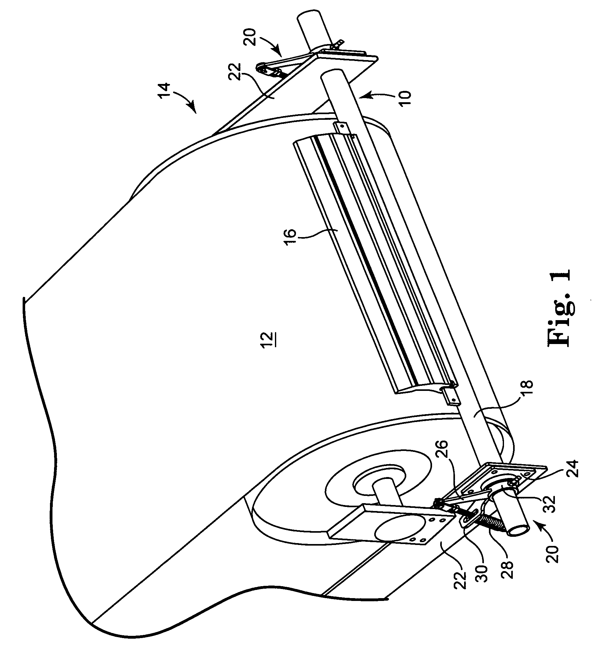
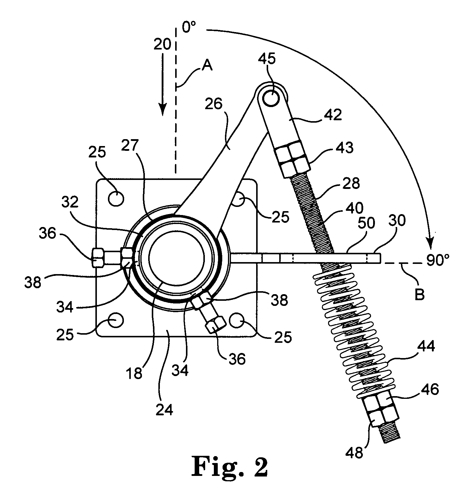
[0002]The present invention pertains to a belt scraper tensioning assembly that is mountable to a shaft of a belt scraper assembly and to a mounting arm of a belt conveyor machine that supports the belt scraper assembly. The belt scraper tensioning assembly comprises a mounting plate, a bearing housing containing a cylindrical bearing, a tensioning arm, a tensioning rod assembly and a stationery arm. The mounting plate has a central opening and is configured for connection to the mounting arm. The bearing housing is connected to a planar surface of the mounting plate. The bearing housing has an inner cylindrical surface that is generally coaxial relative to the central opening of the mounting plate. The cylindrical bearing is positioned within the bearing housing in contact with the inner cylindrical surface. The tensioning arm has a first end and a second end. The first end of the tensioning arm is connected to and extends radially from an outer surface of a cylindrical sleeve. The cylindrical sleeve has a first cylindrical portion and a second cylindrical portion. The second cyl

Problems solved by technology

As the moisture content of the bulk material increases, there is a tendency for some of the material to stick to the conveyor belt.
Due to the abrasive nature of the bulk material being transported, over time the portion of the scraper blade in contact with the conveyor belt wears.

Method used


Image

  • Belt scraper tensioning assembly
  • Belt scraper tensioning assembly
  • Belt scraper tensioning assembly

Examples


Embodiment Construction

[0008]In the following Detailed Description, reference is made to the accompanying drawings, which form a part hereof, and in which is shown by way of illustration specific embodiments in which the invention may be practiced. In this regard, directional terminology, such as “top,”“bottom,”“front,”“back,”“leading,”“trailing,” etc., is used with reference to the orientation of the Figure(s) being described. Because components of embodiments can be positioned in a number of different orientations, the directional terminology is used for purposes of illustration and is in no way limiting. It is to be understood that other embodiments may be utilized and structural or logical changes may be made without departing from the scope of the present invention. The following detailed description, therefore, is not to be taken in a limiting sense, and the scope of the present invention is defined by the appended claims.

[0009]FIG. 1 is a perspective view of a belt scraper assembly 10 for cleaning ...


PUM


Abstract

A belt scraper tensioning assembly attaches to a belt conveyor machine to bias a scraper blade toward a conveyor belt. The tensioning assembly is fully assembled prior to mounting to the belt conveyor. The tensioning assembly comprises a mounting plate with a central opening and a cylindrical bearing housing connected to the mounting plate coaxial with the central opening. A cylindrical bearing is positioned within the bearing housing. A tensioning arm extends radially from a cylindrical sleeve. A portion of the cylindrical sleeve is pivotally mounted within the cylindrical bearing. The cylindrical sleeve is positionable over and connectable to a shaft carrying a belt scraper such that the tensioning arm pivots as the shaft rotates. A stationery arm is connected to the mounting plate and extends along a horizontal axis of the mounting plate. The stationery arm includes an elongate slot. A tensioning rod extends through the elongate slot and has one end connected to the free end of the tensioning arm when the tensioning arm is angularly displaced less than 90 degrees from the stationery arm. A portion of the tensioning rod that extends below the stationery arm carries a spring between the stationery arm and a nut threaded on a lower end of the tensioning rod. The spring can be compressed to urge the tensioning arm toward the stationery arm and thereby rotate the belt scraper shaft to keep the belt scraper blade in close contact with the conveyor belt as the scraper blade wears.

Description

BACKGROUND OF THE INVENTION[0001]The present invention is directed to conveyor belt cleaning apparatus and more specifically to a tensioning assembly for maintaining close contact between a scraper blade of a conveyor belt cleaning apparatus and a conveyor belt of a belt conveyor machine. Belt conveyor machines are commonly used in the construction and mining industries to transport loose bulk material, such as sand, gravel, concrete, asphalt, coal, ore, waste, earth, etc. As the moisture content of the bulk material increases, there is a tendency for some of the material to stick to the conveyor belt. Conveyor belt cleaning apparatus typically comprise a scraper blade mounted on a pivotable shaft that is turn pivotably mounted near the return belt pulley of the conveyor machine. A tensioning mechanism associated with the shaft biases the scraper blade toward the conveyor belt to remove material from the belt before the return travel of the belt. Due to the abrasive nature of the bu...

Claims


Application Information

Patent Timeline
IPC IPC(8): B65G45/16
CPCB65G45/16
Inventor FELTON, JARROD J.
Owner SUPERIOR INDUSTRIES
Why Eureka
Eureka Blog
Learn More