Stop-rotor rotary wing aircraft

a rotary wing and stop-rotor technology, applied in the field of aircraft designs, can solve the problems of less practicality of the counter-rotating fuselage and tail of some “nose sitter” designs, and significant loss of altitud

Active Publication Date: 2010-09-16
THE UNITED STATES OF AMERICA AS REPRESENTED BY THE SECRETARY OF THE NAVY
View PDF1 Cites 76 Cited by
  • Summary
  • Abstract
  • Description
  • Claims
  • Application Information

AI Technical Summary

Problems solved by technology

These designs can also suffer a significant loss in altitude during transition from helicopter to airplane mode, and involve uneven weight distributions, rendering the aircraft “top heavy” and unwieldy during takeoff and landing.
Further, the counter-rotating fuselage and tail of some “nose sitter” designs are less practical than aircraft designs with a conventional fuselage orientation and tail rotor.
“Tilt rotor” configurations with tiltable rotating propellers also involve mechanically complex systems and decreased hover efficiency due to higher disk loading.
“Tail-sitter” designs, so named because the aircraft takes off and lands from a tail-down orientation, are associated with poor hover efficiency due to high disk loading and an awkward 90 degree attitude change between hover and forward flight modes.
At higher speeds, the rotor system does not drive the aircraft and is substantially unloaded by the lift of the wing.
Compound designs also have disadvantages: they are heavy due to additional systems and can suffer a significant download penalty when hovering due to the presence of the wing in the rotor downwash.
The canard rotor wing configuration contemplates a rotor that stops in flight and acts as a fixed wing, but it too suffers drawbacks.
The shape of its airfoil compromises between forward and reverse airflow directions, leading to reduced performance in both flight modes.
Similarly, tilt duct designs, whose propellers are shrouded in ducts and rotate between flight modes, suffer from poor hover efficiency and high drag in forward flight mode.

Method used


Image

  • Stop-rotor rotary wing aircraft
  • Stop-rotor rotary wing aircraft
  • Stop-rotor rotary wing aircraft

Examples


Embodiment Construction

,” one will understand how the features of this invention provide several advantages over current aircraft designs.

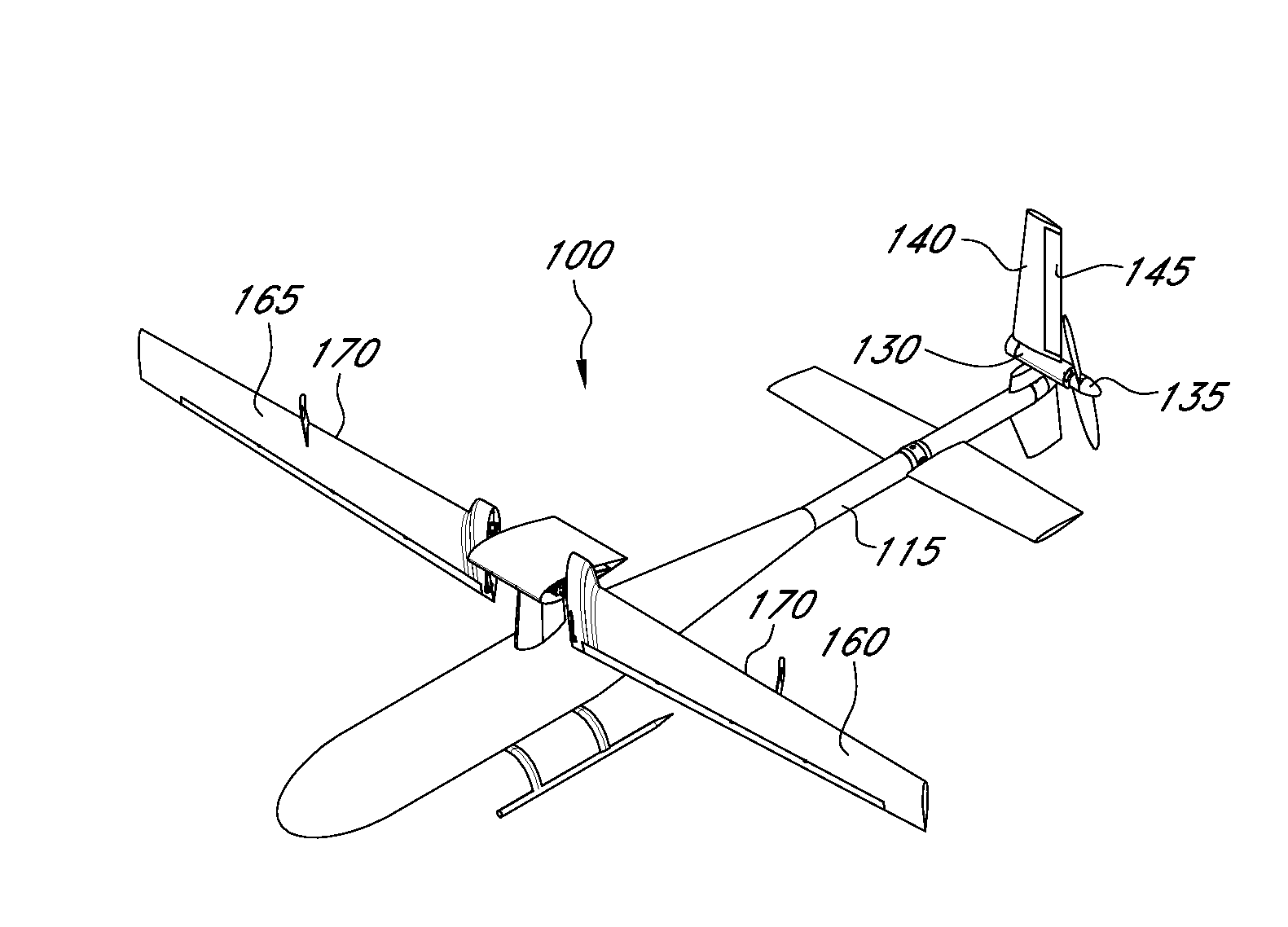
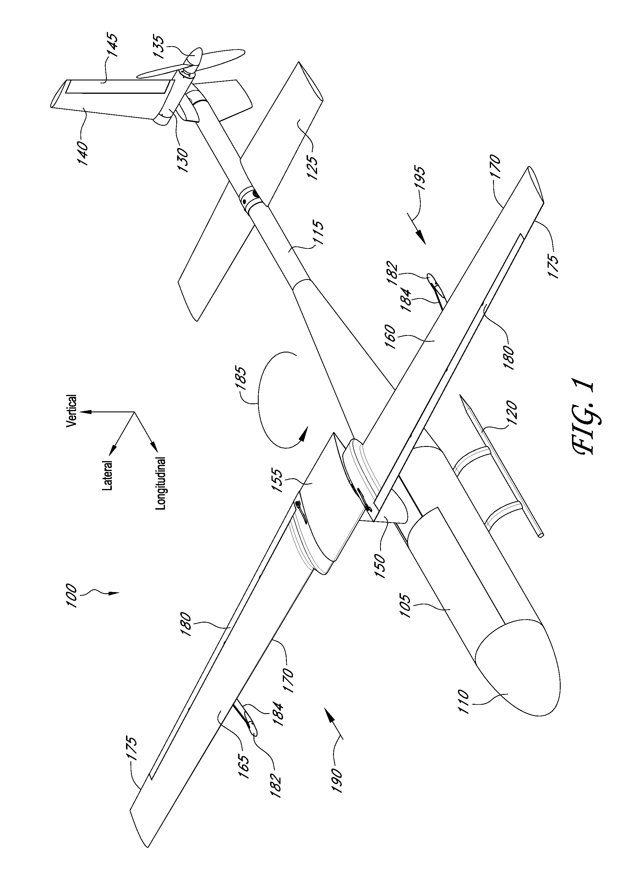
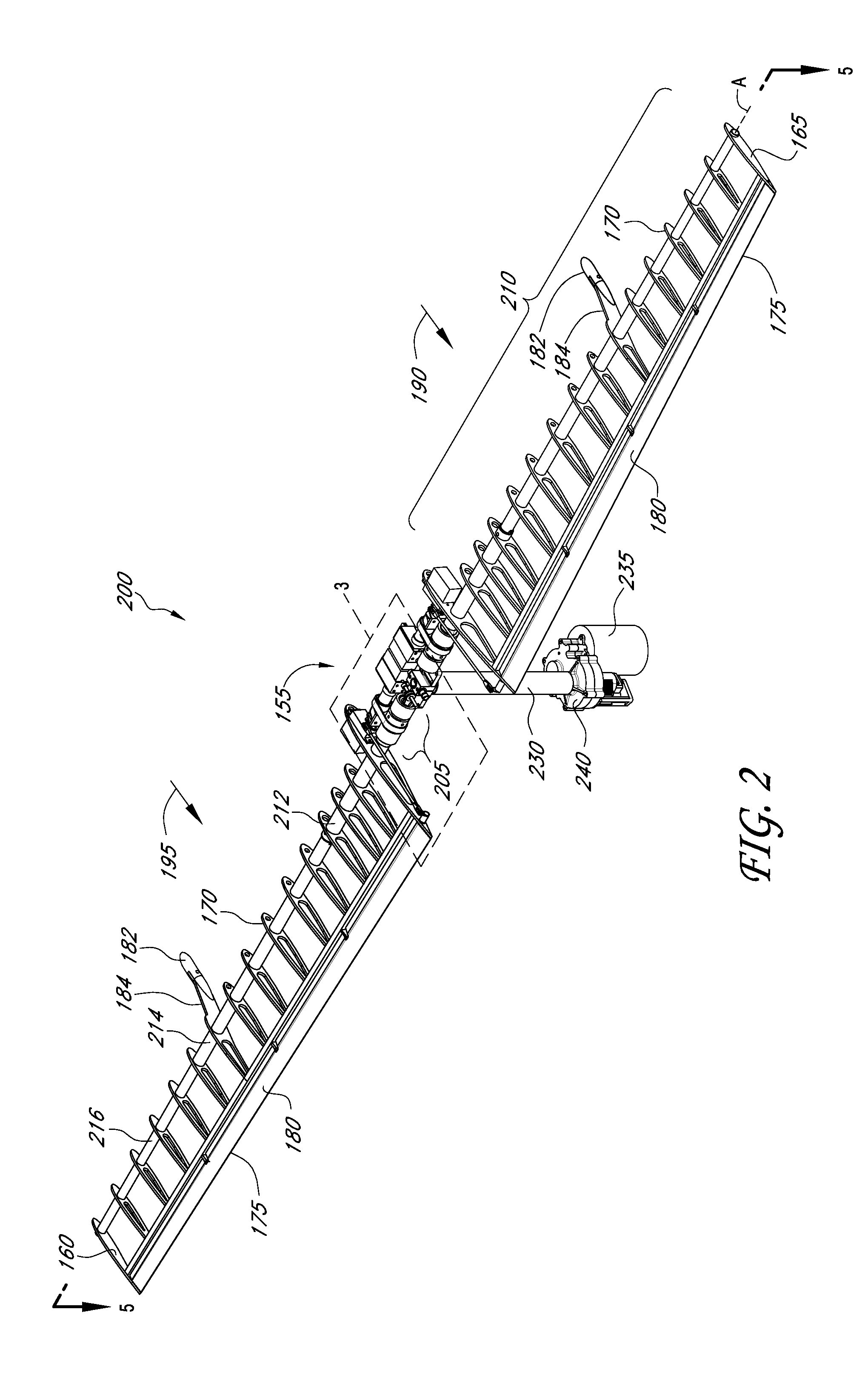
[0008]One embodiment is an aircraft capable of helicopter and fixed wing flight modes. The aircraft includes a plurality of wings, each wing having a spar and a flap movable with respect to the spar; a flap actuator configured to move the flap; and a center section rotatably coupled to each spar and including at least one spar actuator. The spar actuator is configured to rotate at least one of the plurality of wings about a rotational axis of the spar when the aircraft transitions between helicopter and fixed wing flight modes.

[0009]Another embodiment is method for transitioning an aircraft between flight modes. The method includes changing the motion of a center section of the aircraft relative to a fuselage of the aircraft from a first flight mode to a second flight mode, where the direction of relative airflow over one of a plurality of wings reverses when the aircra...


PUM


Abstract

Systems and methods for transitioning an aircraft between helicopter and fixed wing flight modes are provided. In one embodiment, an aircraft comprises a plurality of wings each having a spar and a flap; a flap actuator configured to move the flap with respect to the spar; and a center section rotatably coupled to each spar. The center section includes at least one spar actuator configured to rotate at least one of the wings about a rotational axis of the spar when the aircraft transitions between helicopter and fixed wing flight modes.

Description

CROSS-REFERENCE TO RELATED APPLICATIONS[0001]This application is a non-provisional of and claims priority under 35 U.S.C. Section 119(e) to U.S. Provisional Application 61 / 094,794, filed Sep. 5, 2008. The entire content of this provisional application is hereby incorporated by reference in its entirety.BACKGROUND[0002]1. Field of the Invention[0003]The invention relates generally to unmanned aircraft designs, and, more particularly, to aircraft designs that combine the features of helicopter and fixed wing aircraft.[0004]2. Description of the Related Art[0005]Some unmanned aircraft designs attempt to combine the vertical takeoff and landing (VTOL) and hover capabilities of a helicopter and the increased speed and range capabilities of fixed wing airplanes. Stop rotor “nose sitter” configurations, so named because the aircraft takes off and lands from a nose-down orientation, may offer good hover efficiency and aerodynamic design but can require complex mechanical systems. These desi...

Claims


Application Information

Patent Timeline
Patent Type & Authority Applications(United States)
IPC IPC(8): B64C27/24
CPCB64C27/24B64C2201/108B64C2201/102B64C39/024B64U30/12B64U30/20
Inventor TAYMAN, STEVEN K.
Owner THE UNITED STATES OF AMERICA AS REPRESENTED BY THE SECRETARY OF THE NAVY
Why Eureka
Try Eureka