
Logically partitioned networking devices

a networking device and partition technology, applied in the field of logical partitioned networking devices, can solve the problems of cumbersome use of vlan technology to create numerous l2 parallel network-wide segments, prone to configuration errors, and inability to adapt to the needs of users, etc., and achieve the effect of increasing the complexity of vlan technology, and increasing the difficulty of vlan technology

Active Publication Date: 2010-09-16
CISCO TECH INC
View PDF24 Cites 168 Cited by
  • Summary
  • Abstract
  • Description
  • Claims
  • Application Information

AI Technical Summary

Benefits of technology

[0018]Logical partitioning of networking devices may include a data packet identifying a particular logical partition or virtual networking device (VND) with which the data packet desires to interact. Identification may be performed by including a header in the data packet that identifies the VND that is to route and/or forward the data packet. The header may be a VLAN tag identifying the logical partition. For example, as the data packet is read by the networking device, the networking device may examine the header and determine that the data packet is associated with the first VND. The first VND may be a logical partition resident on the net

Problems solved by technology

Issues may arise when segmented networks are used with logically partitioned networking devices.
The use of VLAN technology to create numerous L2 parallel network-wide segments may be cumbersome, unreliable, and prone to configuration errors.
Proliferation may be a problem because a large number of networking devices in the WAN would have to be configured to accept the segmentation of the network.
As a result, VLAN technology has become increasingly complicated.
The use of L2 access control lists between the VLAN segments may have complicated management and security.
However, issues may occur with network segmentation schemes (e.g., vNETs and VPNs) that are used with network devices that are logically partitioned.
Thus, it may be difficult to use logically partitioned network devices with vNET networking environments.
Furthermore, elements may not be drawn to scale.

Method used


Image

  • Logically partitioned networking devices
  • Logically partitioned networking devices
  • Logically partitioned networking devices

Examples


Embodiment Construction

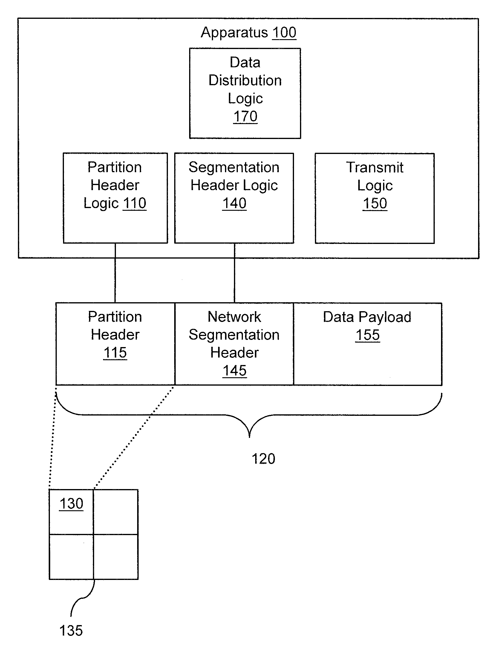
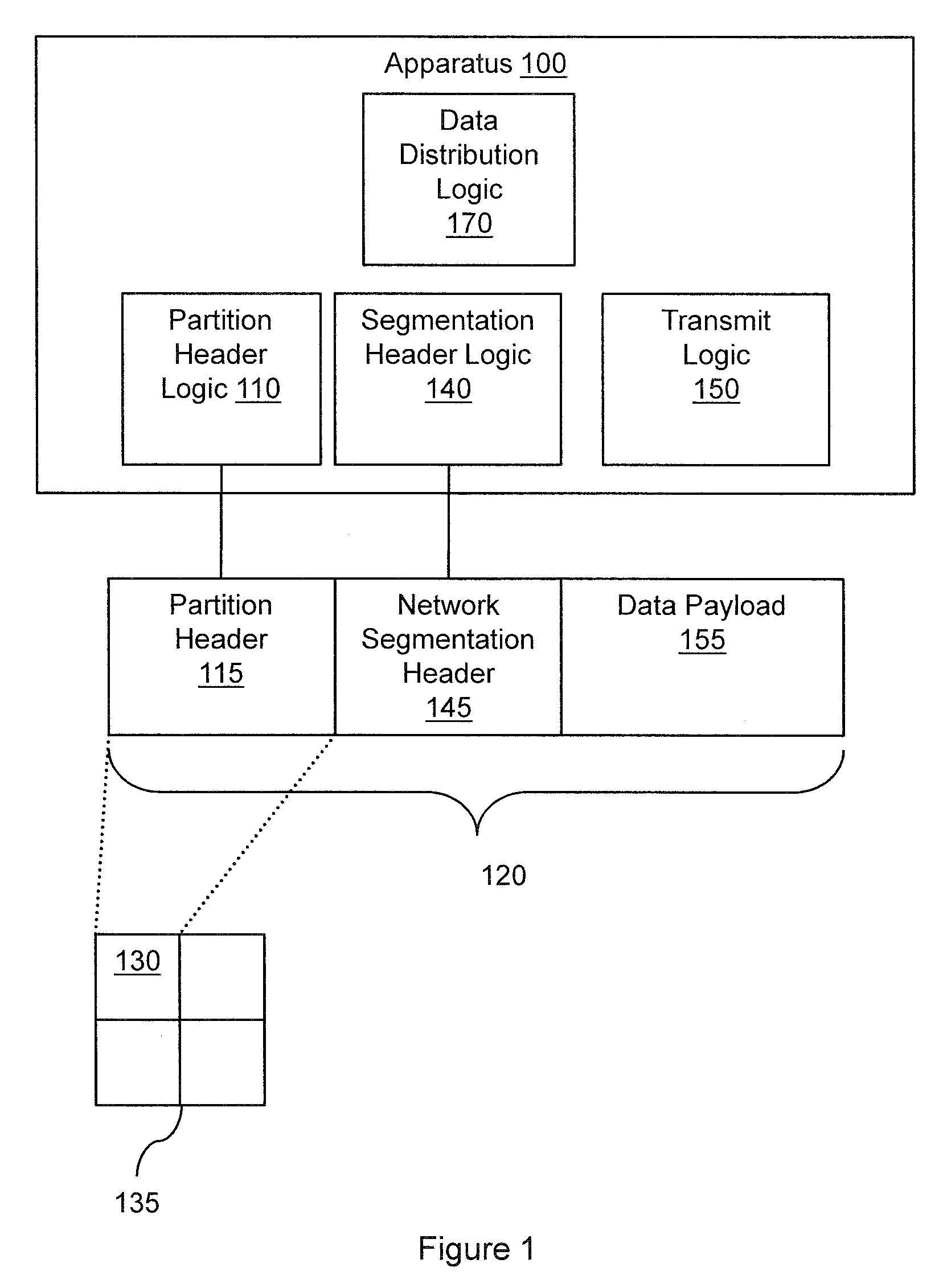
[0023]FIG. 1 illustrates an apparatus 100 associated with logically partitioned networking devices. Apparatus 100 includes a partition header logic 110 to insert a partition header 115 into a data packet 120. The partition header 115 may identify a member 130 of a set of logical partitions 135. In one embodiment, the set of logical partitions 135 may partition a networking device. The networking device may be a gateway, a router, a networking switch, and so on.

[0024]“Logic”, as used herein with respect to FIGS. 1, 2, and 8 includes but is not limited to hardware, firmware, software in execution on a machine, and / or combinations of each to perform a function(s) or an action(s), and / or to cause a function or action from another logic, method, and / or system. Logic may include a software controlled microprocessor, a discrete logic (e.g., ASIC), an analog circuit, a digital circuit, a programmed logic device, a memory device containing instructions, and so on. Logic may include one or mo...


PUM


Abstract

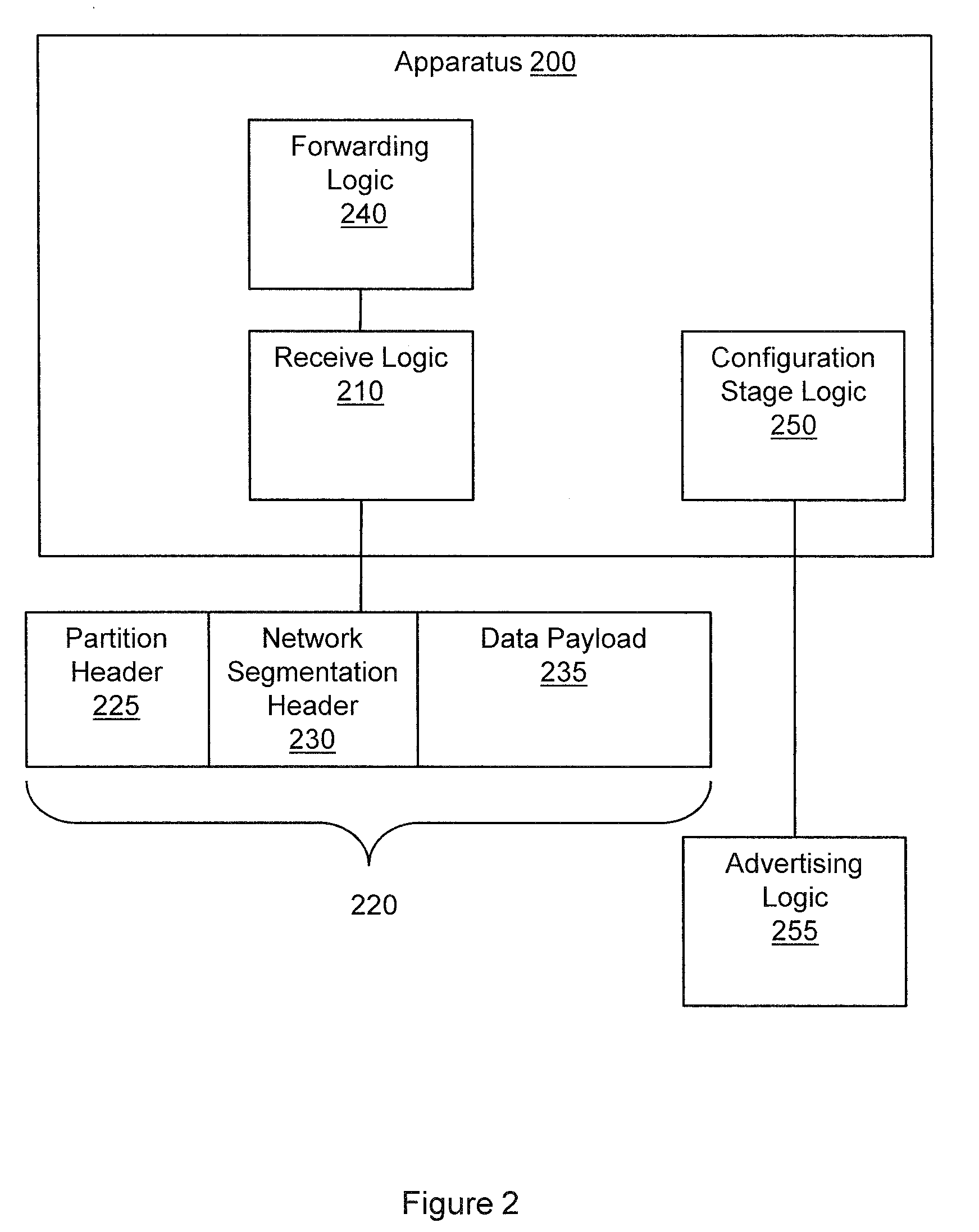
Systems, methods, and other embodiments associated with logically partitioned networking devices are described herein. One example method includes receiving a message from a common interface. The message comprises a logical partition header (LPH) and a network segmentation header (NSH). The LPH may be associated with a logical partition of a networking device. The NSH is associated with a grouping (e.g., segmentation) of networking devices. The example method may also include forwarding the message to the grouping of networking devices based, at least in part, on the NSH and a virtual route forwarding (VRF) table. Forwarding the message to the logical partition of the networking device based, at least in part, on the LPH.

Description

CROSS REFERENCE TO RELATED APPLICATIONS[0001]This application is related to the following U.S. patent application, which is assigned to the present assignee:[0002]“SYSTEM AND METHODS FOR NETWORK SEGMENTATION”, Ser. No. 11 / 226,011, Filing Date: Sep. 14, 2005, Inventors: Jim Guichard, Warren Wainner, Saul Adler, Khalil Jabr, and S. Scott Van De Houten, Docket: CPOL 61759.BACKGROUND[0003]Sophisticated networking devices have enough resources to support multiple logical instances of the networking device. Thus, a networking device may be logically partitioned to into multiple sets of resources so that each set of resources can be operated independently with its own operating system and / or applications. Issues may arise when segmented networks are used with logically partitioned networking devices.[0004]Many enterprises wish to run multiple network segments within the same campus, wide area network (WAN), or data center environment. A network segment may be associated with a virtual loca...

Claims


Application Information

Patent Timeline
IPC IPC(8): H04L12/56H04L12/28
CPCH04L12/465H04L12/4666H04L45/02H04L45/00H04L12/4641H04L12/4645H04L45/50
Inventor JABR, KHALILVAN DE HOUTEN, S. SCOTTMORENO, VICTOR M.
Owner CISCO TECH INC
Learn More