Transmitting and receiving apparatus having plural antenna in multi-user environments and method thereof
a multi-user environment and transmitting and receiving technology, applied in the field of radio transmitting and receiving apparatus, can solve the problems of difficult system application of limited research on almost all of the mimo technologies in the related art, and inability to achieve high-speed radio data rate, etc., to achieve the effect of reducing influence, increasing data rate of radio communication system, and effective use of limited radio resources
- Summary
- Abstract
- Description
- Claims
- Application Information
AI Technical Summary
Benefits of technology
Problems solved by technology
Method used
Image
Examples
fourth embodiment
Multi-Stream Transmission Method Based on Water-Filling Algorithm
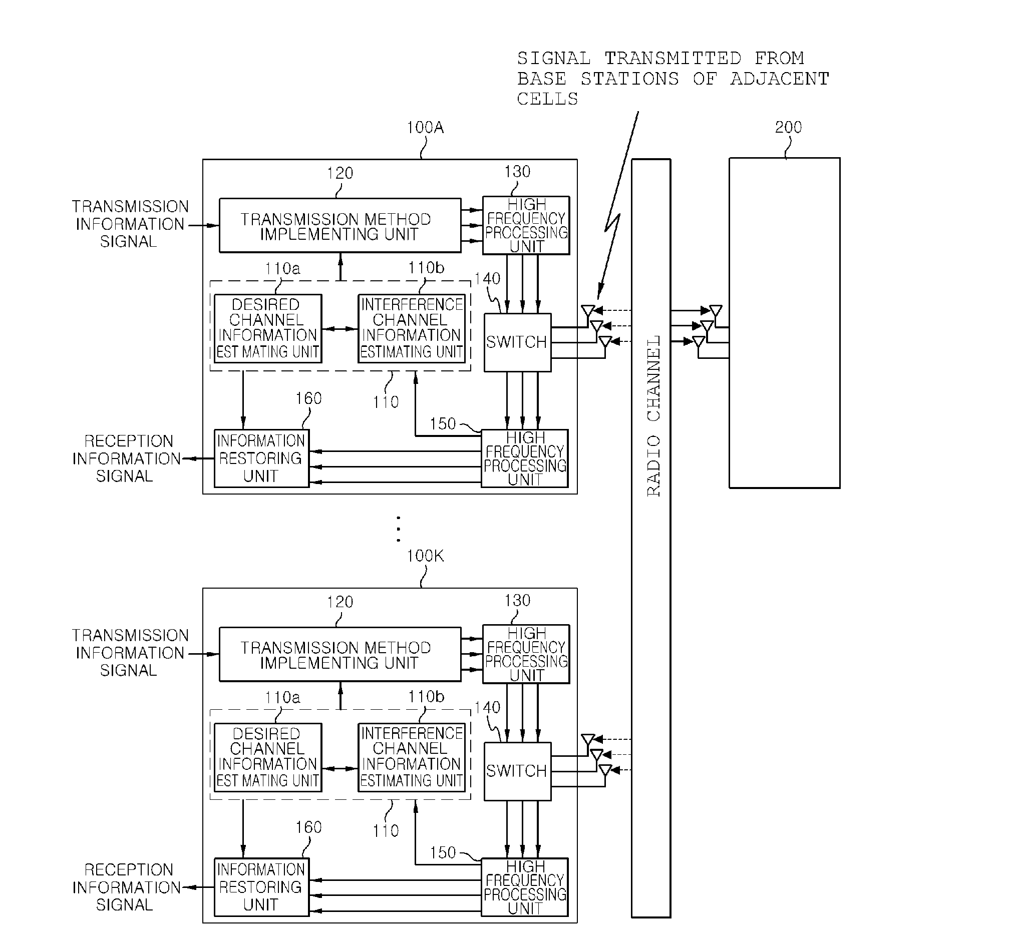
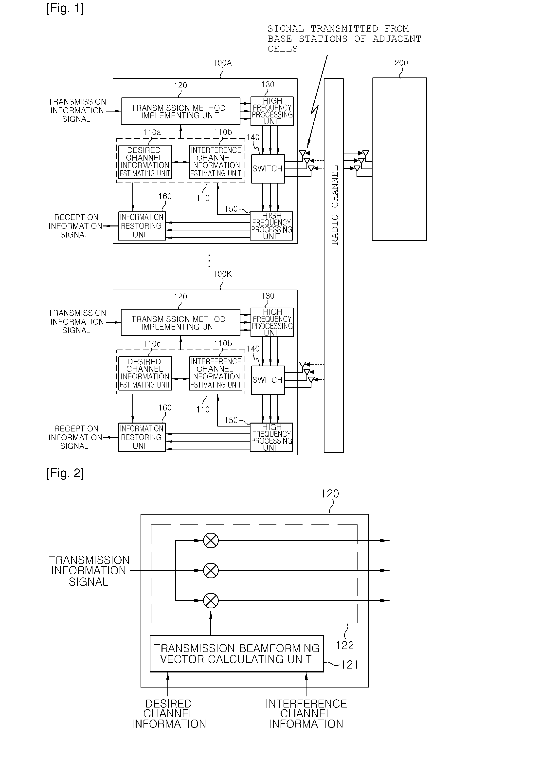
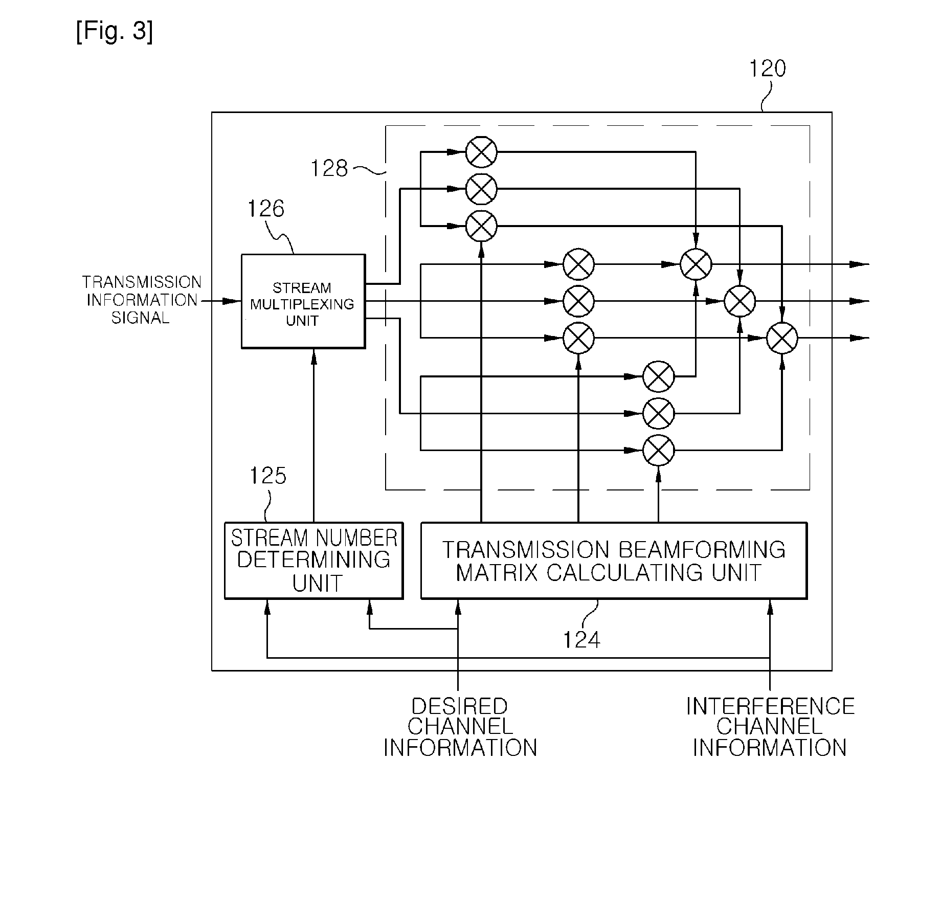
[0090]When using the multi-stream transmission method based on the water-filling algorithm, a beamforming matrix that is used by the terminal of the m-th cell is assumed as Wm(2). At this time, Wm(2) is a matrix (Nt×Ns(2)) that is composed of Ns(2) column vectors. In this case, Ns(2) denotes the number of streams that are simultaneously transmitted. In the multi-stream transmission method based on the water-filling algorithm, the number of streams Ns(2) and the transmission beamforming matrix are determined on the basis of the water-filling algorithm. Referring to FIG. 5, the channel information estimating unit 110 estimates desired channel information and interference channel information (S10). If a transmission weighting value determination method in the transmission method implementing unit 120 is selected as a maximum SGINR transmission beamforming scheme (S15), the transmission beamforming matrix calculating unit ...
fifth embodiment
Transmission Method Implementation Method Based on a Maximum Interference Permissible Amount
[0095]If a maximum interference permissible amount of the m-th cell is defined as bm, the transmission method implementing unit 120 implements a transmission method while limiting a total sum of interference on adjacent cells to the maximum interference permissible amount or less, as represented by Math Figure 14. In this case, the maximum interference permissible amount means a maximum permissible amount of interference on adjacent cells from a transmitting terminal.
MathFigure14Hi(m)Wm2≤βm[Math.14]MathFigure15Wm=argmaxWmlog2det(I+(Hd(m)Wm)(Hd(m)Wm)H)[Math.15]
[0096]subject to
∥Hi(m)Wm∥2≦βm
[0097]Since Math FIG. 15 is related to a convex problem, a solution can be calculated using a convex optimization algorithm.
[0098](Multi-User Transmission Method that not only Considers Performance of a Corresponding Cell but also an Influence Due to Interference on Adjacent Cells During a Downlink)
[0099]FIG...
first embodiment
Non-Interference Transmission Beamforming Scheme
[0233]The non-interference transmission beamforming scheme is a transmission beamforming scheme that maximizes a data rate with respect to the k-th terminal under the condition where the base station 1300 does not interfere with the other terminals except for the k-th terminal in the corresponding cell and the terminals of the adjacent cells, when it is assumed that the base station 1300 transmits a data signal to the k-th terminal in the corresponding cell. In the non-interference transmission beamforming method, a transmission beamforming vector that is used when a data signal is transmitted to the k-th terminal of the m-th cell can be represented by Math Figure 28.
MathFigure28w(m,k)1=argmaxwheff(m,m,k)downwsubjecttoheff(m,m,k′)downw=0forallk′(k′∈Smandk′≠k),heff(m,n,k″)downw=0forallnandk″(n≠mandk″∈Sn)[Math.28]
[0234]In this case,
[0235]heff(m,n,k)down denotes an effective channel vector (1×Nb) that is obtained by multiplying a receptio...
PUM
 Abstract
Description
Claims
Application Information
 - R&D
- Intellectual Property
- Life Sciences
- Materials
- Tech Scout
- Unparalleled Data Quality
- Higher Quality Content
- 60% Fewer Hallucinations
Browse by: Latest US Patents, China's latest patents, Technical Efficacy Thesaurus, Application Domain, Technology Topic, Popular Technical Reports.
© 2025 PatSnap. All rights reserved.Legal|Privacy policy|Modern Slavery Act Transparency Statement|Sitemap|About US| Contact US: help@patsnap.com


