Detector, detection method, and integrated circuit for detection

a detection method and integrated circuit technology, applied in the field of image processing technology, can solve the problems of a large memory, a high-performance processor, a comparatively low processing power, etc., and achieve the effect of higher-speed processing and efficient detection of the specified imag

Inactive Publication Date: 2010-09-16
PANASONIC INTELLECTUAL PROPERTY CORP OF AMERICA
View PDF7 Cites 60 Cited by
  • Summary
  • Abstract
  • Description
  • Claims
  • Application Information

AI Technical Summary

Benefits of technology

[0020]Since the positions of the matching target ranges are set so that each matching target range overlaps a neighboring matching target range by a predetermined overlap width, there is an increased possibility of the detector having the above structure pertaining to the present invention detecting a specified image that is partially included in each of a plurality of matching target ranges, even when the specified image cannot be detected when the positions of the matching target ranges are set so that the matching target ranges do not overlap each other.
[0021]Also, the detector may further include a scaling ratio determination unit operable to determine a ratio for the portion of the input image encompassed by each matching target range, wherein the setting of the position of each matching target range by the setting unit may be performed so that the overlap width corresponds to the ratio determined by the scaling ratio determination unit, and the matching of the portion of the input image encompassed by each matching target range and the template image may be performed after a size of the portion of the input image encompassed by the matching target range has been changed according to the ratio determined by the scaling ratio determination unit.
[0022]Accordingly, since the overlap width corresponds to the ratio determined by the scaling ratio determination unit, the detector pertaining to the present invention can detect the specified image more efficiently than a case in which the overlap width is arbitrary.
[0023]Also, the detection target area may be a square area that is a portion of the input image, each matching target range may be a square area that is a portion of the detection target area, and the ratio for the portion of the input image encompassed by each matching target range may be one of a plurality of reduction ratios, and the detector may further include: a storage unit operable to store therein information indicating, for each reduction ratio, the overlap width corresponding to the reduction ratio, wherein the determination of the ratio by the scaling ratio determination unit and the setting of the position of each matching target range by the setting unit may be performed in accordance with the information stored in the storage unit, and the matching unit may include a reduction unit operable to, for each reduction ratio determined by the scaling ratio determination unit, reduce the portion of the input image by the reduction ratio.
[0024]According to this structure, since the overlap width that each matching target range overlaps a neighboring matching target range is stored for each reduction ratio, and the position of each matching target range is set accordingly, the detector pertaining to the present invention can perform higher-speed processing compared to a case in which the positions of the matching target areas are calculated on a case-by-case basis.
[0025]Also, since for each reduction ratio determined by the scaling ratio determination unit, an image reduced by the reduction ratio is matched to the template image, the detector pertaining to the present invention can detect a specified image having a different size from the template image without using a plurality of template images.

Problems solved by technology

Therefore, an issue arises that a comparatively high-performance processor, a large capacity memory, or the like is necessary when attempting to detect the specified image in a short time period.
Since the vehicle is only detected, etc. in the detection target area, even when the size of the input image (the high-resolution image) is comparatively large, this enables suppressing the throughput amount and causing processing to be performed by a processor, etc. that has comparatively low processing power.

Method used


Image

  • Detector, detection method, and integrated circuit for detection
  • Detector, detection method, and integrated circuit for detection
  • Detector, detection method, and integrated circuit for detection

Examples


embodiment 1

[0061]Overview

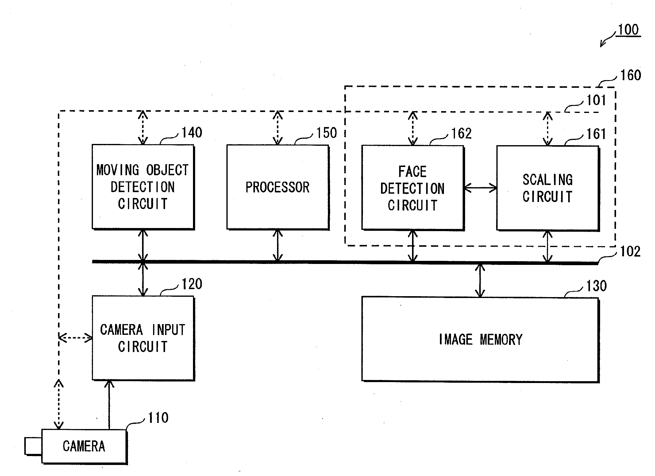
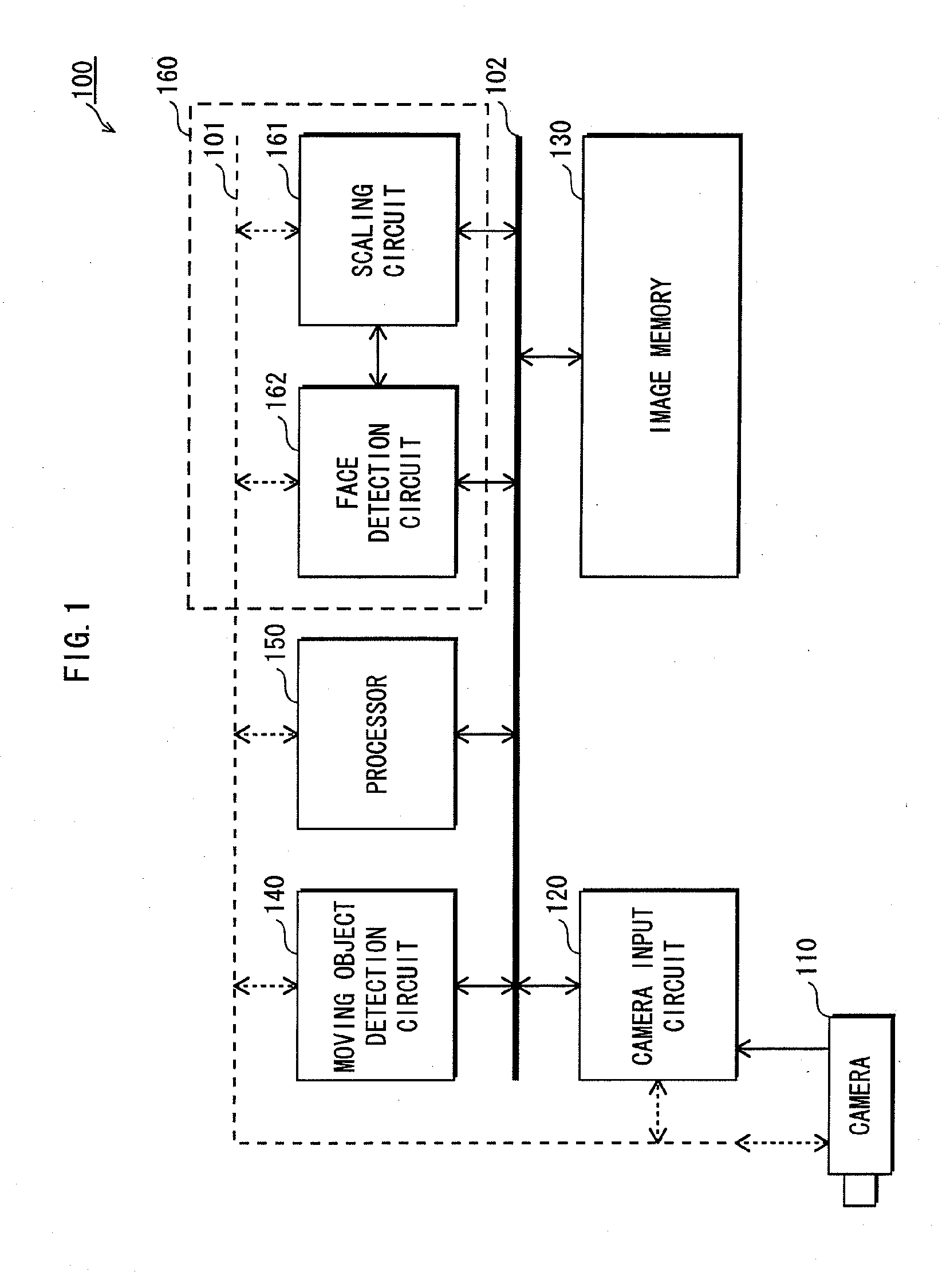
[0062]The face detector pertaining to embodiment 1 detects a face image that is less than or equal to a predetermined size (for example, QVGA size (320×240 pixels)) by processing a detection target area in units of the predetermined size. The detection target area is an area in which the face image is anticipated to exist.

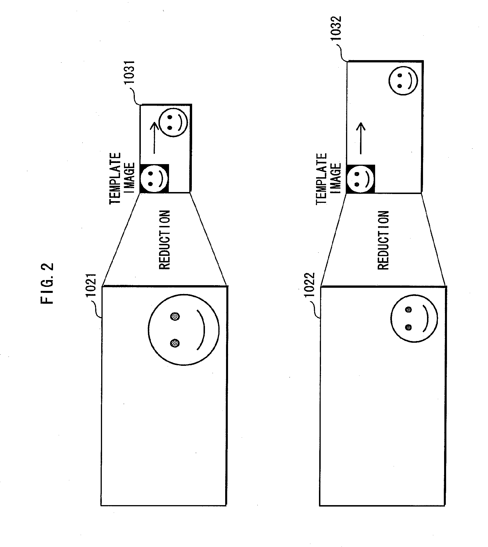
[0063]The following describes the processing performed in units of the predetermined size by the face detector. Specifically, the face image is detected by setting the positions of a plurality of ranges (matching target areas) each having a predetermined size, so that the detection target area is covered by the matching target areas and each matching target area overlaps a neighboring matching target area by a predetermined width (hereinafter referred to as “overlap”), and matching, each time a matching target area is set, an image that is a reduction of the portion of the input image in the matching target area (hereinafter referred to as a “reduced ...

embodiment 2

[0172]Overview

[0173]Although in the description of embodiment 1, the moving object detection circuit 140 performs processing for detecting the moving object, the following describes an example in which the face detector performs the processing to detect the moving object.

[0174]In addition to the functions of the face detector 160 pertaining to embodiment 1, the face detector pertaining to the present embodiment attempts to detect the face image at a predetermined spacing interval, for each piece of high-resolution image data stored sequentially in the image memory 130, with use of the entire high-resolution image data as the detection target area.

[0175]Hereinafter, “entire detection” refers to detecting the face image with use of the entire high-resolution image data as the detection target area. “Partial detection” refers to detecting the face image with use of a portion of the high-resolution image data as the detection target area, as described in embodiment 1.

[0176]When the face...


PUM


Abstract

A detector detects a specified image in an input image. The detector includes an area determination unit for determining, in the input image, a detection target area in which the specified image potentially exists, a setting unit for setting positions of a plurality of matching target ranges substantially in the detection target area, each of the matching target ranges being a predetermined size, so that the matching target ranges cover the detection target area, and each matching target range overlaps a neighboring matching target range by a predetermined overlap width, and a matching unit for detecting the specified image by matching a portion of the input image encompassed by each matching target range set by the setting unit and a template image for detecting the specified image.

Description

TECHNICAL FIELD[0001]The present invention relates to image processing technology, and in particular to technology for detecting a predetermined image in an input image.BACKGROUND ART[0002]There is a known method for detecting, in an input image, a specified image (for example, an image of a face) that is smaller than the input image, by matching a template image that is a template for detecting the specified image to the input image. In this method, a template image of a predetermined size that is smaller than the square input image is moved gradually from the top left to the bottom right of the input image, and repeatedly matched to the input image. Therefore, an issue arises that a comparatively high-performance processor, a large capacity memory, or the like is necessary when attempting to detect the specified image in a short time period.[0003]As a method for solving the above problem, an area (hereinafter referred to as a “detection target area”) that is only a portion of the ...

Claims


Application Information

Patent Timeline
Patent Type & Authority Applications(United States)
IPC IPC(8): G06K9/62
CPCG06K9/00228G06V40/161
Inventor TOMITA, HIROTOFUCHIGAMI, IKUO
Owner PANASONIC INTELLECTUAL PROPERTY CORP OF AMERICA
Why Eureka
Try Eureka