

Golf ball
a golf ball and ball technology, applied in the field of golf balls, can solve the problems of golf players not being able to decide the hitting place of golf balls, golf balls having a large difference in trajectory, and not conforming to the rules, etc., and achieves excellent aerodynamic symmetry, excellent flight performance, and superior dimple effect.
Inactive Publication Date: 2010-09-16
SUMITOMO RUBBER IND LTD
View PDF5 Cites 8 Cited by
- Summary
- Abstract
- Description
- Claims
- Application Information
AI Technical Summary
Benefits of technology
[0032]In the golf ball, a superior dimple effect is achieved. The golf ball has excellent flight performance. The golf ball also has excellent aerodynamic symmetry.
Problems solved by technology
A golf ball having a large difference between a trajectory during PH rotation and a trajectory during POP rotation, that is, inferior aerodynamic symmetry, does not conform to the rules.
Other than a shot at a teeing ground, golf players cannot decide a hitting place of a golf ball.
Thus, a flight distance of a golf ball with inferior aerodynamic symmetry varies.
Golf players have difficulty in landing this golf ball at an intended point.
Such a golf ball has inferior aerodynamic symmetry.
However, the uniqueness is not sufficiently eliminated.
This golf ball has insufficient aerodynamic symmetry.
The flight distance of the golf ball is insufficient.
Method used
View moreImage
Smart ImageViewing Examples

Examples
examples
[0115]The following will show the effects of the present invention by means of Examples, but the present invention should not be construed in a limited manner based on the description of these Examples.
Login to View More PUM
 Abstract
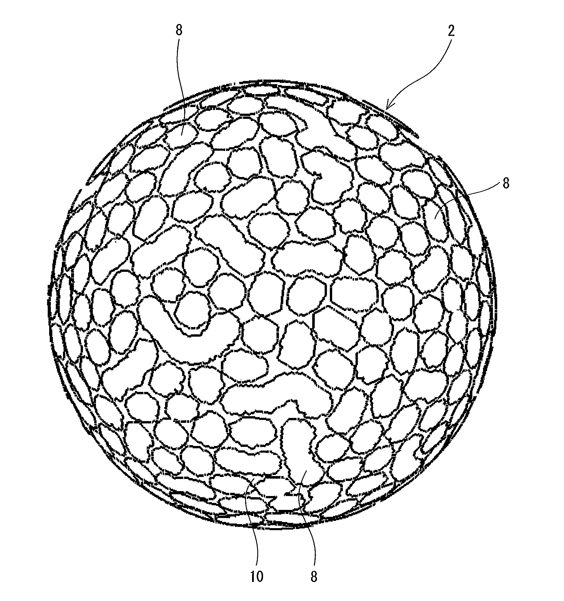
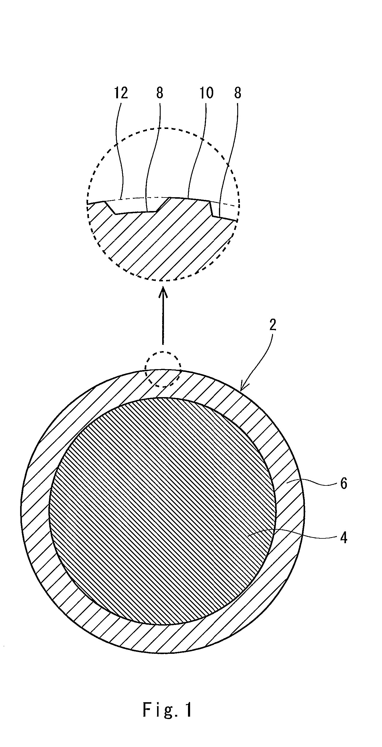
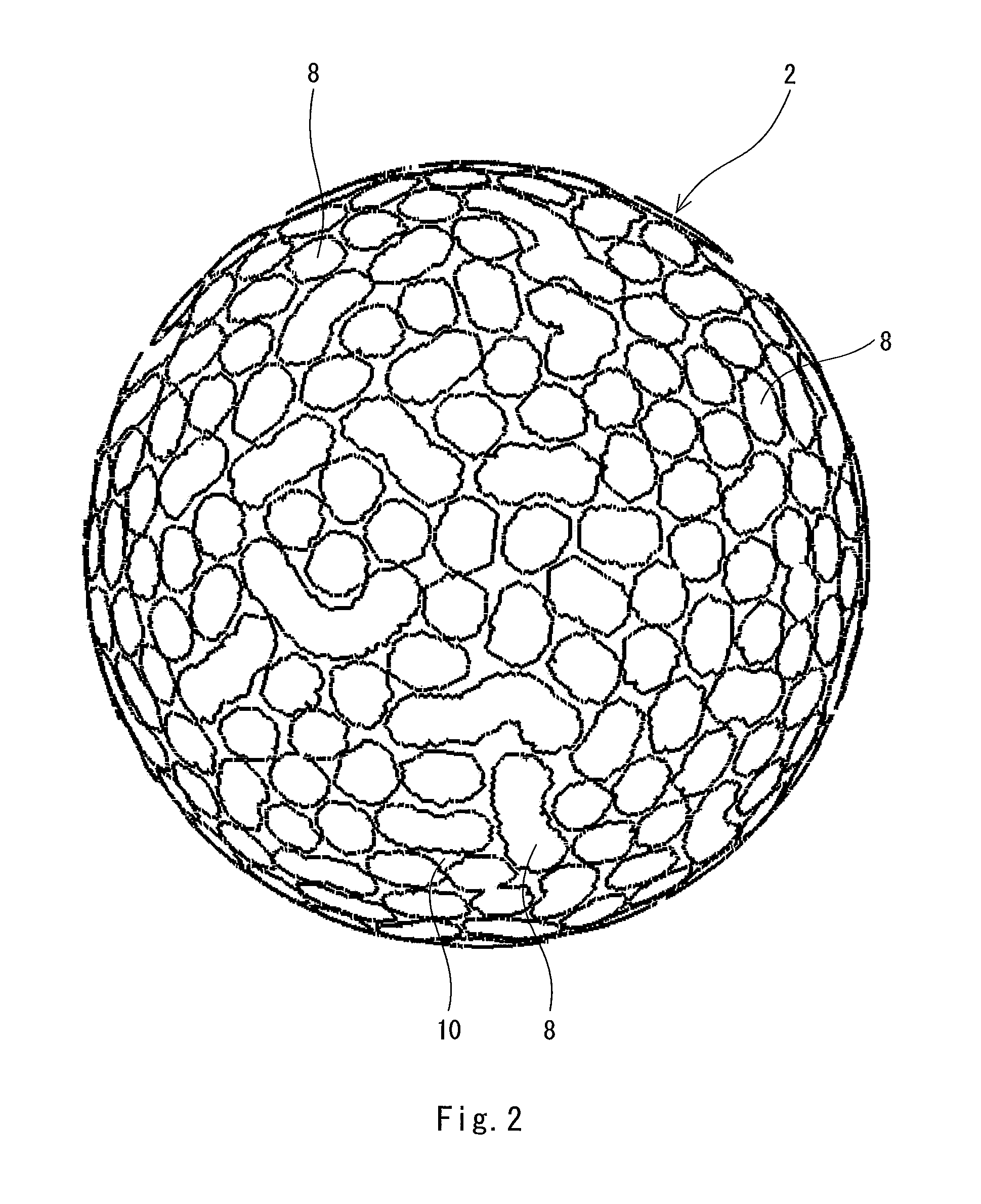
A golf ball 2 has a large number of dimples 8 and a land 10. A rugged pattern is formed on the surface of the golf ball 2 by these dimples 8 and the land 10. These dimples 8 are arranged in a random manner. Each dimple 8 has a crater shape. For designing the rugged pattern, a Cellular Automaton method is used. A fluctuation range Rh of the golf ball 2 that is an index indicating the aerodynamic characteristic during PH rotation is 1.9 mm or less. A fluctuation range Ro of the golf ball 2 that is an index indicating the aerodynamic characteristic during POP rotation is 1.9 mm or less. The absolute value of the difference dR between the fluctuation range Ro and the fluctuation range Rh is 0.4 mm or less.
Description
[0001]This application claims priority on Patent Application No. 2009-60401 filed in JAPAN on Mar. 13, 2009. The entire contents of this Japanese Patent Application are hereby incorporated by reference.BACKGROUND OF THE INVENTION[0002]1. Field of the Invention[0003]The present invention relates to golf balls. Specifically, the present invention relates to improvement in dimples of golf balls.[0004]2. Description of the Related Art[0005]Golf balls have a large number of dimples on the surface thereof. The dimples disturb the air flow around the golf ball during flight to cause turbulent flow separation. By causing the turbulent flow separation, separation points of the air from the golf ball shift backwards leading to a reduction of drag. The turbulent flow separation promotes the displacement between the separation point on the upper side and the separation point on the lower side of the golf ball, which results from the backspin, thereby enhancing the lift force that acts upon the ...
Claims
Login to View More Application Information
Patent Timeline
 IPC IPC(8): A63B37/14
CPCA63B37/0004A63B37/0006A63B37/0007A63B37/0017A63B37/0021A63B37/0083A63B37/0033A63B37/0035A63B37/0064A63B37/008A63B37/0022A63B37/00215A63B37/00221
InventorKIM, HYOUNGCHOLONUKI, MASAHIDEYAMADA, KANAME
OwnerSUMITOMO RUBBER IND LTD