Current measuring device

a current measuring and current technology, applied in the direction of instruments, inductances, base element modifications, etc., can solve the problems of time-consuming and costly process of physically inspecting and identifying relays, and the number of different faults

Active Publication Date: 2010-09-23
CONSOL EDISON OF NEW YORK +1
View PDF16 Cites 68 Cited by
  • Summary
  • Abstract
  • Description
  • Claims
  • Application Information

AI Technical Summary

Benefits of technology

[0007]According to one aspect of the invention, a current measuring device is provided having a cover coupled to a base. A magnetic shield member is coupled to the base. A compliant member is coupled to the magnetic shield member. A Hall effect device is coupled to the cover adjacent the magnetic shield member.
[0008]According to another aspect of the invention, a current sensor is provided including a housing having a cover and a base. The housing having a first opening on a first side and a second opening on a second side opposite the first opening. The base further having a semi-cylindrical surface extending between the first opening and the second opening. A fastener is couples the cover to the base. A magnetic shielding member is coupled to the semi-cylindrical surface. A compliant member is coupled to the magnetic shielding member. A Hall effect device is coupled to the cover opposite the compliant member. A current sensing circuit is mounted within the housing and electrically coupled to the Hall effect device.
[0009]In accordance with another aspect of the invention, a current sensor for measuring electrical current flow through an electrical conductor is provided. The current sensor includes a cover having a substantially planar first surface and a wall extending around the first surface. The cover includes a first semicircular opening in a first side of the cover wall and a second semicircular opening in a second side of the cover wall opposite the first semicircular opening. A base is coupled to the cover, the base having a substantially planar second surface and a wall extending around the second surface, the base wall having a third semicircular opening in a first side of the base wall adjacent the first semicircular opening and a fourth semicircular opening in a second side of the base wall adjacent the second semicircular opening, the base further having a semi-cylindrical surface extending between the third semicircular opening and the fourth semicircular opening. A Hall effect device is coupled to the cover opposite the semi-cylindrical surface. A compliant member is coupled to the semi-cylindrical surface between the semi-cylindrical surface and the Hall effect device. A current sensing circuit is coupled to the cover and electrically coupled to the Hall effect device.

Problems solved by technology

During transmission of the electrical power, a number of different faults may occur due to events such as vegetation growth and lightening strikes for example.
Thus, the process of physically inspecting and identifying the relay may be time consuming and costly.

Method used


Image

  • Current measuring device
  • Current measuring device
  • Current measuring device

Examples


Embodiment Construction

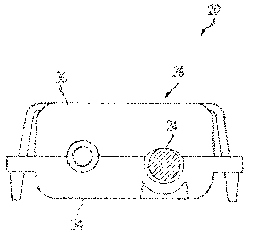
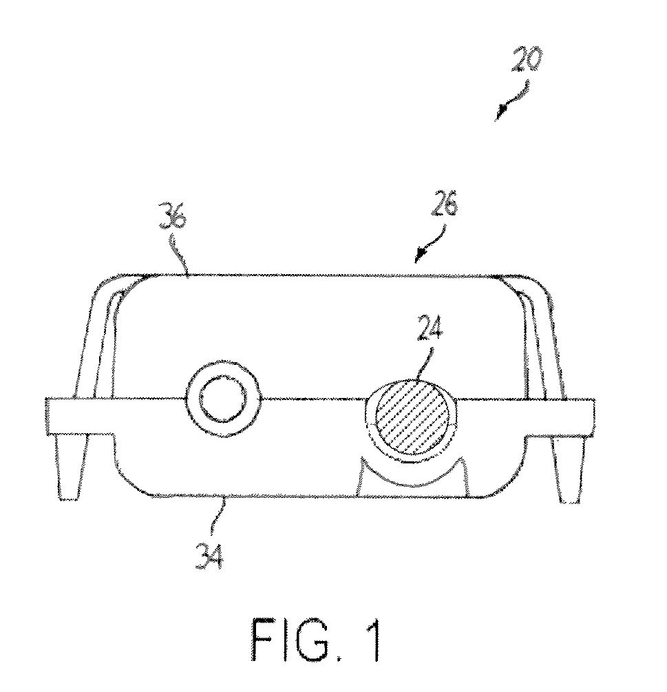
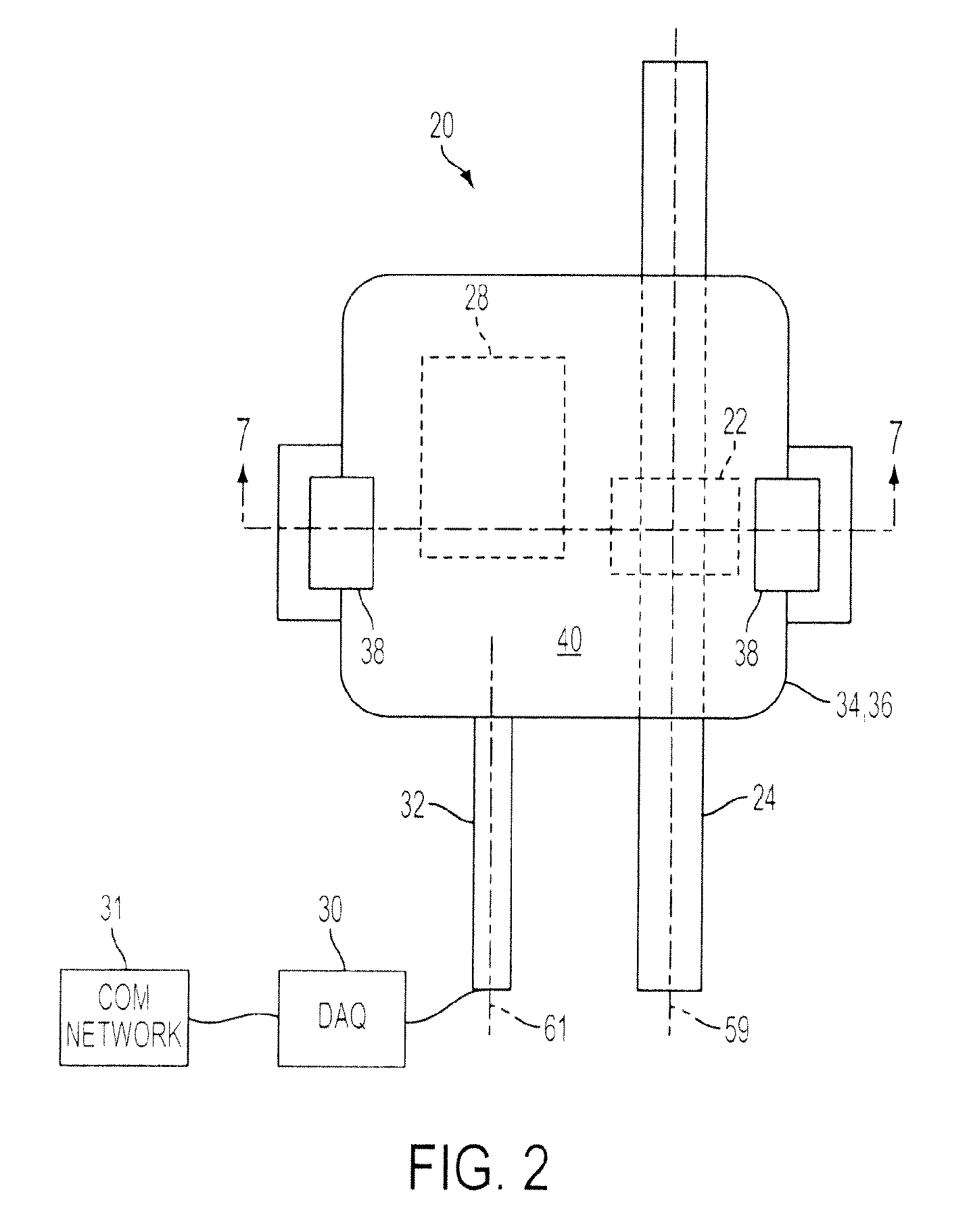
[0019]FIG. 1-2 illustrates an exemplary embodiment of a current sensor device 20. The current sensor 20 includes a Hall effect device 22 that is placed in contact with an electrical conductor 24 by a clamping force created by the housing assembly 26. In the exemplary embodiment, the Hall effect device 22 is an integrated circuit that includes a transducer that varies its output voltage in response to changes in a magnetic field. When electrical current passes through the electrical conductor 24, a magnetic field is created. In response to the magnetic field, the Hall effect sensor 22 produces an electrical signal that is proportional to the magnetic field and the electrical current flowing through the electrical conductor 24. In a typical application, such as with electrical conductors associated with protective relays for example, Hall effect sensor 22 is capable of sensing a current between 0.2 to 40.0 amps passing through electrical conductor 24.

[0020]A current sensing circuit 28...


PUM


Abstract

A current sensor is provided for non-invasively measuring electrical current in an electrical conductor. The current sensor includes a housing having a Hall effect device and circuitry for transmitting a signal indicative of the current flowing through the electrical conductor. The current sensor includes a base having a surface for supporting an electrical conductor. A magnetic shielding member is coupled to the surface to shield the Hall effect device from stray or external magnetic fields. A compliant member is coupled to the magnetic shielding member opposite the surface. The compliant member compresses to allow the current sensor to accommodate a large variety of electrical conductor sizes. The compliant member further acts to bias the electrical conductor against the Hall effect device.

Description

BACKGROUND OF THE INVENTION[0001]The present invention relates generally to a device for the noninvasive measurement of electrical current through a conductor and in particular to a device that may be installed in the field for measuring electrical current with a Hall effect sensor.[0002]Electrical power is typically produced at centralized power production facilities and transferred at high voltages to local substations. The local substations transform the electrical power to a medium or low voltage. The electrical power is subsequently distributed through feeders to local distribution networks. The power is thus delivered to an end customer that consumes the electrical power.[0003]Since the electrical power is often transmitted over long distances, reliability and integrity of the system are major considerations in the design of the transmission system. During transmission of the electrical power, a number of different faults may occur due to events such as vegetation growth and l...

Claims


Application Information

Patent Timeline
Patent Type & Authority Applications(United States)
IPC IPC(8): G01R33/07
CPCG01R33/025G01R15/202G01R33/072G01R1/22
Inventor BOSE, SANJAYGIULIANTE, ANTHONY T.MAKKI, AMIRWALSH, JOHNVODA, DOUGLASFRANKLIN, TIMOTHY
Owner CONSOL EDISON OF NEW YORK
Why Eureka
Try Eureka