
Use of optical reflectance proximity detector for nuisance mitigation in smoke alarms

a proximity detector and optical reflectance technology, applied in the field of smoke alarms, can solve the problems of not having a convenient method of discontinuing the loud, shrill alarm, and certain types of false alarm indications that are often very annoying to users

Active Publication Date: 2010-09-23
GOOGLE LLC
View PDF36 Cites 88 Cited by
  • Summary
  • Abstract
  • Description
  • Claims
  • Application Information

AI Technical Summary

Benefits of technology

The present invention is a smoke detection system that can detect smoke and generate an alarm. It also has the ability to detect if an object is close to the smoke alarm and deactivate the alarm for a certain period of time. This helps to prevent false alarms and ensures that the system is always working effectively.

Problems solved by technology

While the smoke alarms are very effective at notifying individuals of the possible existence of fire that is generating the smoke, certain types of false alarm indications may often be very annoying to a user.
This may cause the creation of enough smoke that will set off the smoke alarm causing the loud, shrill alarm.
Presently, there exists no method for easily discontinuing the loud, shrill alarm other than fanning the atmosphere in the area of the smoke alarm in an attempt to remove the smoke from the area that is causing the smoke alarm to activate or removing the battery or house power from the smoke alarm in order to turn it off.
Removal of the power source may be difficult as smoke alarms are usually mounted upon the ceiling or other high area of the house or building to provide maximum smoke detection capabilities.
An additional problem with existing smoke alarms is the battery check or low battery condition.
An additional related problem relates to the low battery condition within a smoke alarm.
Unfortunately, this beep often occurs in early morning hours when the house temperature is at a minimum and these conditions maximize the low battery condition and increase the likelihood of an alarm.
This is of course a most irritating time for this to occur.
Additionally, the beep is very difficult to locate since the beep is short and a single high frequency tone.
Due to the reflections and use of half wavelengths shorter than the distance between the human ears, it is very difficult to localize the source which may present a problem since most homes normally include a number of smoke alarms.

Method used


Image

  • Use of optical reflectance proximity detector for nuisance mitigation in smoke alarms
  • Use of optical reflectance proximity detector for nuisance mitigation in smoke alarms
  • Use of optical reflectance proximity detector for nuisance mitigation in smoke alarms

Examples


Embodiment Construction

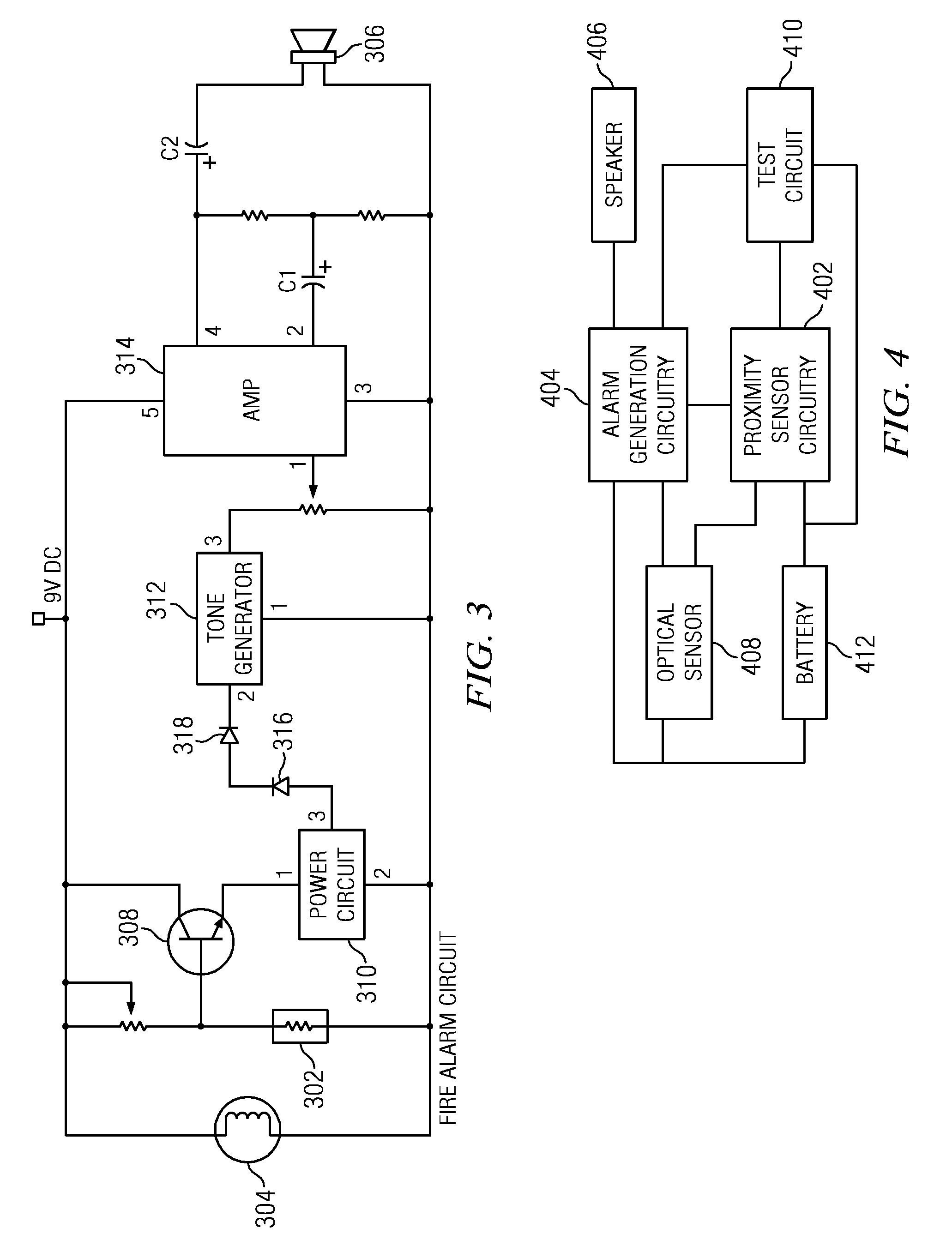
[0016]Referring now to the drawings, wherein like reference numbers are used herein to designate like elements throughout, the various views and embodiments of a smoke alarm having proximity detection operation mode are illustrated and described, and other possible embodiments are described. The figures are not necessarily drawn to scale, and in some instances the drawings have been exaggerated and / or simplified in places for illustrative purposes only. One of ordinary skill in the art will appreciate the many possible applications and variations based on the following examples of possible embodiments.

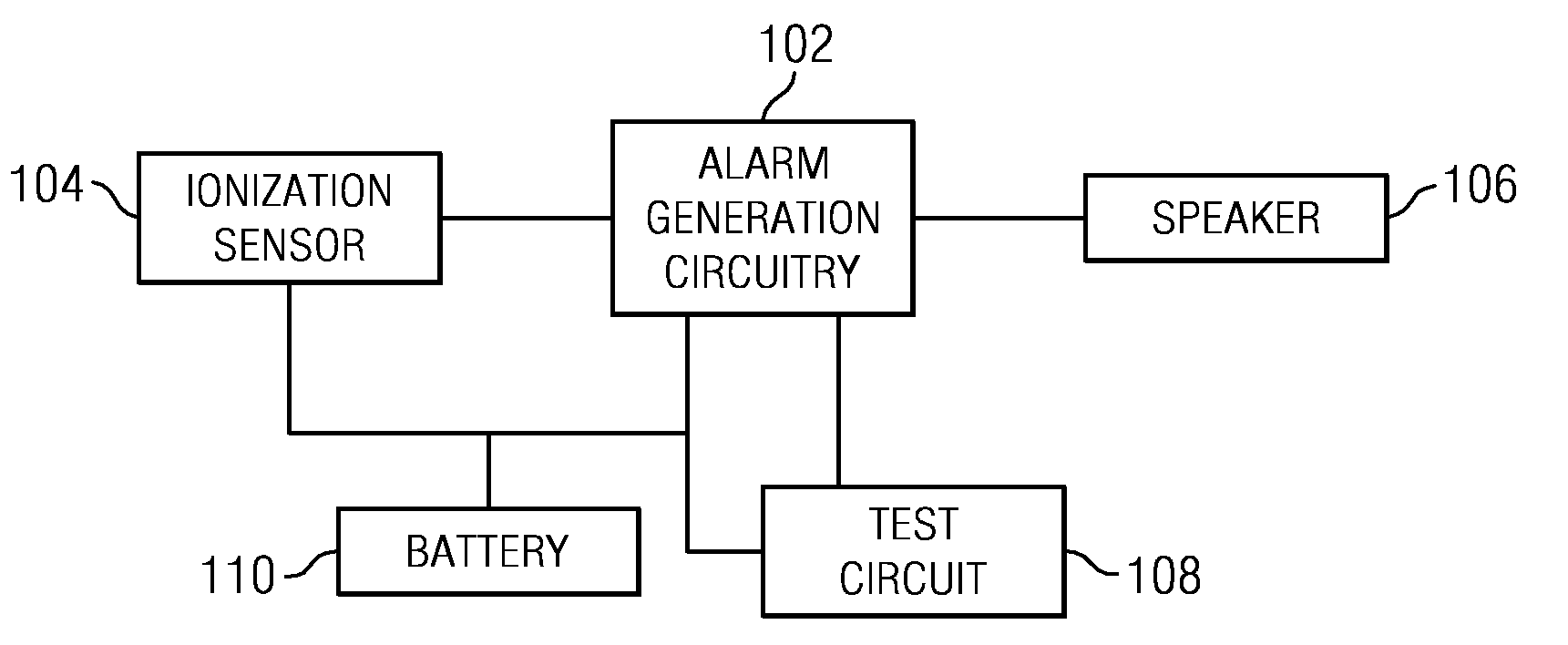
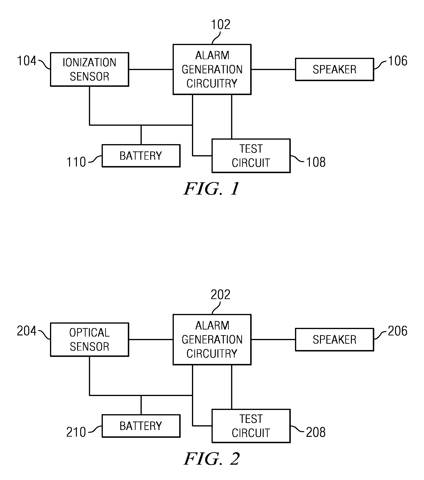
[0017]Referring now to the drawings, and more particularly to FIG. 1, there is illustrated a functional block diagram of a first type of smoke alarm. The smoke alarm of FIG. 1 utilizes ionization detection to detect smoke. The alarm generation circuitry 102 is associated with an ionization sensor 104. The ionization sensor 104 detects particles of smoke using a small amount of radioact...


PUM


Abstract

A smoke alarm comprises smoke detection circuitry for detecting smoke and generating a detection signal responsive thereto. Proximity detection circuitry generates a proximity detection signal responsive to detection of an object within in a selected distance of the smoke alarm. Alarm generation circuitry generates an audible alarm responsive to the detection signal. The audible alarm may be deactivated for a predetermined period of time responsive to at least one proximity detection signal.

Description

CROSS-REFERENCE TO RELATED APPLICATIONS[0001]This application claims the benefit of U.S. Provisional Application for Patent Ser. No. 61 / 162,193, filed on Mar. 20, 2009, and entitled “USE OF OPTICAL REFLECTANCE PROXIMITY DETECTOR FOR NUISANCE MITIGATION IN SMOKE ALARMS,” the specification of which is incorporated herein by reference.TECHNICAL FIELD[0002]The present invention relates to smoke alarms, and more particularly to smoke alarms including proximity detectors for controlling operation of the smoke alarm.BACKGROUND[0003]Smoke alarms are utilized for detecting and warning the inhabitants of a home or other occupied location of the existence of smoke which may indicate a fire. Upon detection of the smoke by the smoke alarm, the device emits a shrill, loud alarm that notifies all individuals within the area that smoke has been detected and departure from the premises may be necessary.[0004]While the smoke alarms are very effective at notifying individuals of the possible existence...

Claims


Application Information

Patent Timeline
Patent Type & Authority Applications(United States)
IPC IPC(8): G08B17/10
CPCG08B3/10G08B17/10G08B29/185G08B17/103G08B17/11G08B29/145
Inventor HOLCOMBE, WAYNE T.
Owner GOOGLE LLC
Learn More