Projection optical system and image display apparatus

a technology of projection optical system and image display apparatus, which is applied in the direction of projectors, telescopes, instruments, etc., can solve the problems of increasing the depth and height of the apparatus, the size of the plane mirror for bending the modulated light is large, and the height size of the image display apparatus cannot be sufficiently reduced, so as to reduce the height of the lower par

Active Publication Date: 2010-09-23
MITSUBISHI ELECTRIC CORP
View PDF3 Cites 56 Cited by
  • Summary
  • Abstract
  • Description
  • Claims
  • Application Information

AI Technical Summary

Benefits of technology

[0010]It is therefore an object of the present invention to provide a projection optical system which enables to reduce a heigh

Problems solved by technology

However, there is a problem that such a projection type image display apparatus requires a space for a projection optical path, thereby a depth and a height of the apparatus increase.
For this reason, there is the following problem: in order to arrange so that a modulated light after the emission from the lens system to the incidence on the convex mirror does not interfere with another element (e.g., a bottom end of a screen), it is required to provide a large space in a lower part below the screen in the image display apparatus, and thus a height size of the image display apparatus cannot be sufficiently reduced (a height of the lower part below the screen).
A projection optical system of the image display apparatus described in th

Method used


Image

  • Projection optical system and image display apparatus
  • Projection optical system and image display apparatus
  • Projection optical system and image display apparatus

Examples


first embodiment

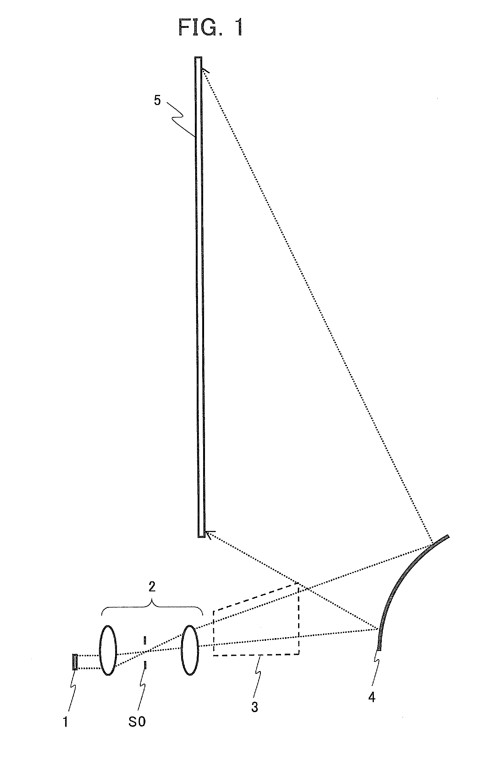
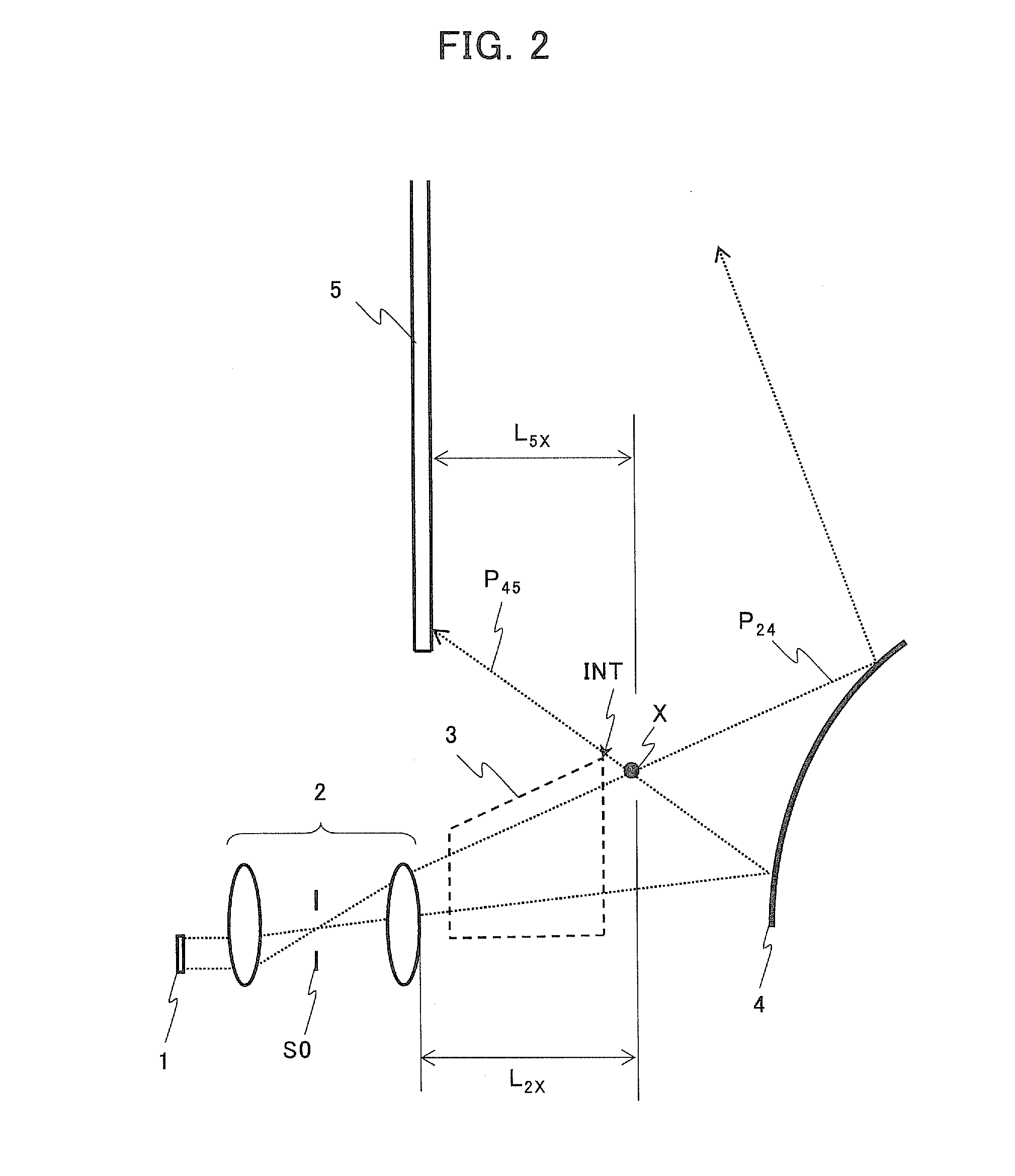
[0066]FIG. 5 is a diagram schematically illustrating an example of an internal structure of the image display apparatus according to a first embodiment of the present invention (an internal structure in a case where it is assumed that no plane mirror is provided). FIG. 6 is a plan view schematically illustrating an example of an internal structure of the image display apparatus according to the first embodiment of the present invention, and FIG. 7 is a schematic side view of the internal structure of the image display apparatus according to the first embodiment when seen in a D7-direction of FIG. 6.

[0067]As shown in FIG. 5 to FIG. 7, the image display apparatus according to the first embodiment has a housing 16, a projection optical system 10 disposed inside the housing 16, and a screen 15 disposed on a front surface of the housing 16, wherein a light flux of a modulated light emitted from the projection optical system 10 is projected onto the screen 15. In the first embodiment, the...

second embodiment

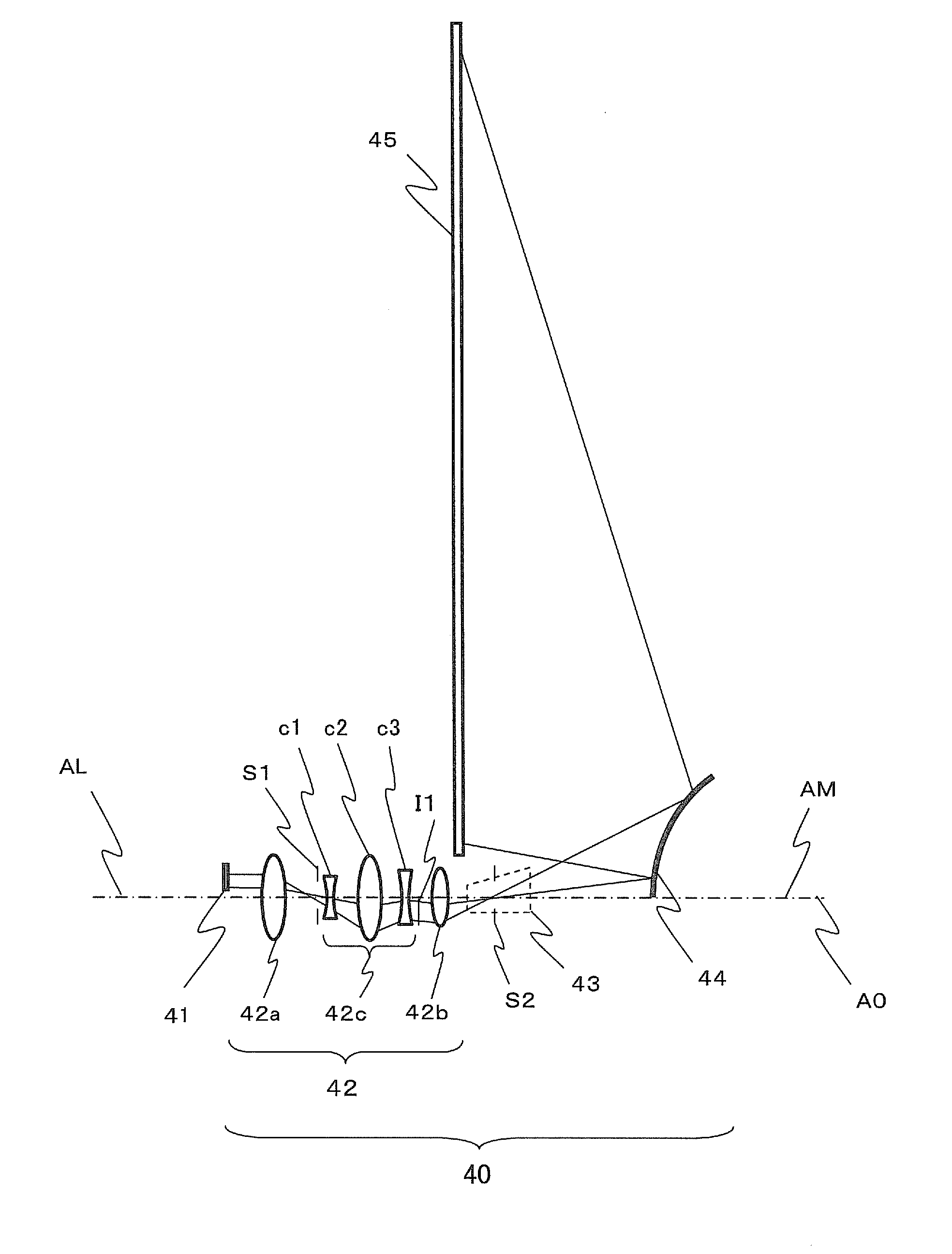
[0102]FIG. 14 is a diagram schematically illustrating an example of an internal structure of an image display apparatus according to the second embodiment of the present invention (an internal structure in a case where it is assumed that no plane mirror is provided). FIG. 15 is a plan view schematically illustrating an example of an internal structure of the image display apparatus according to the second embodiment. An image display panel 21, a lens system 22 (lens groups 22a, 22b), a plane mirror 23, a convex mirror 24 and a screen 25 in FIG. 14 and FIG. 15 correspond to the image display panel 11, the lens system 12 (the lens groups 12a, 12b), the plane mirror 13, the convex mirror 14 and the screen 15 in FIG. 5 and FIG. 6, respectively. A projection optical system 20 according to the second embodiment differs from that of the first embodiment in a point that: a stop S3 in the lens system (lens-system-stop) is disposed nearest to the image display panel 21 in the lens system 22, ...

third embodiment

[0111]FIG. 16 is a diagram schematically illustrating an example of an internal structure of an image display apparatus according to a third embodiment of the present invention (an internal structure in a case where it is assumed that a plane mirror 33 is not provided). FIG. 17 is a plan view schematically illustrating an example of the internal structure of the image display apparatus according to the third embodiment (in a case where the plane mirror 33 is provided). An image display panel 31, a lens system 32 (lens groups 32a, 32b), the plane mirror 33, a convex mirror 34 and a screen 35 in FIG. 16 and FIG. 17 correspond to the image display panel 21, the lens system 22 (the lens groups 22a, 22b), the plane mirror 23, the convex mirror 24 and the screen 25 in FIG. 14 and FIG. 15, respectively. In a projection optical system 30 according to the third embodiment, the optical path in the projection optical system 20 according to the second embodiment is bent in a horizontal directio...


PUM


Abstract

A projection optical system for enlarging and projecting a light flux from an image display panel modulating an irradiation light, onto a screen in an oblique direction, the projection optical system includes: a lens system including a plurality of lenses, the lens system refracting the light flux from the image display panel; a single convex mirror reflecting the light flux from the lens system, the lens system and the convex mirror being arranged in an order from the image display panel; and a stop disposed in an optical path after an emission from the lens system to an incidence on the convex mirror.

Description

BACKGROUND OF THE INVENTION[0001]1. Field of the Invention[0002]The present invention relates to a projection optical system enlarging and projecting a modulated light which has been emitted from a small-size image display panel and an image display apparatus including the projection optical system.[0003]2. Description of the Related Art[0004]A projection type (rear-projection type) image display apparatus is known as a scheme to realize a large-screen image display apparatus at low cost. However, there is a problem that such a projection type image display apparatus requires a space for a projection optical path, thereby a depth and a height of the apparatus increase. As improvement schemes for this, it is proposed that a projection light from a projection optical system which includes a lens system and a power mirror is projected onto a projection surface (a screen surface) not vertically but obliquely, thereby a depth size or a height size of the apparatus are reduced.[0005]For e...

Claims


Application Information

Patent Timeline
IPC IPC(8): G03B21/28G02B27/18G02B17/08
CPCG03B21/28G03B21/10
Inventor KUWATA, MUNEHARUSASAGAWA, TOMOHIRA
Owner MITSUBISHI ELECTRIC CORP
Why Eureka
Try Eureka