Three-dimensional display apparatus

Inactive Publication Date: 2010-09-23
IND TECH RES INST
View PDF5 Cites 23 Cited by
  • Summary
  • Abstract
  • Description
  • Claims
  • Application Information

AI Technical Summary

Benefits of technology

[0010]In view of the foregoing, the three-dimensional display apparatus of the present disclosure employs a patterned half-wave plate having different regions with different phase-retardation which enable the three-dimensional display apparatus to produce left and right eye images with different polarization directions. Also, the three-dimensional display apparatus employs a quarter-wave plate to convert a linearly polarized image into a circularly polarized image, and is used in conjunction with a combination of a quarter-wave plate and a half-wave plate with appropriate optical axis included angles. Therefore, the three-dimensional

Problems solved by technology

However, due to the characteristics of microretarder fabricated by laser scanning, the three-dimensional display apparatus could

Method used


Image

  • Three-dimensional display apparatus
  • Three-dimensional display apparatus
  • Three-dimensional display apparatus

Examples


Example

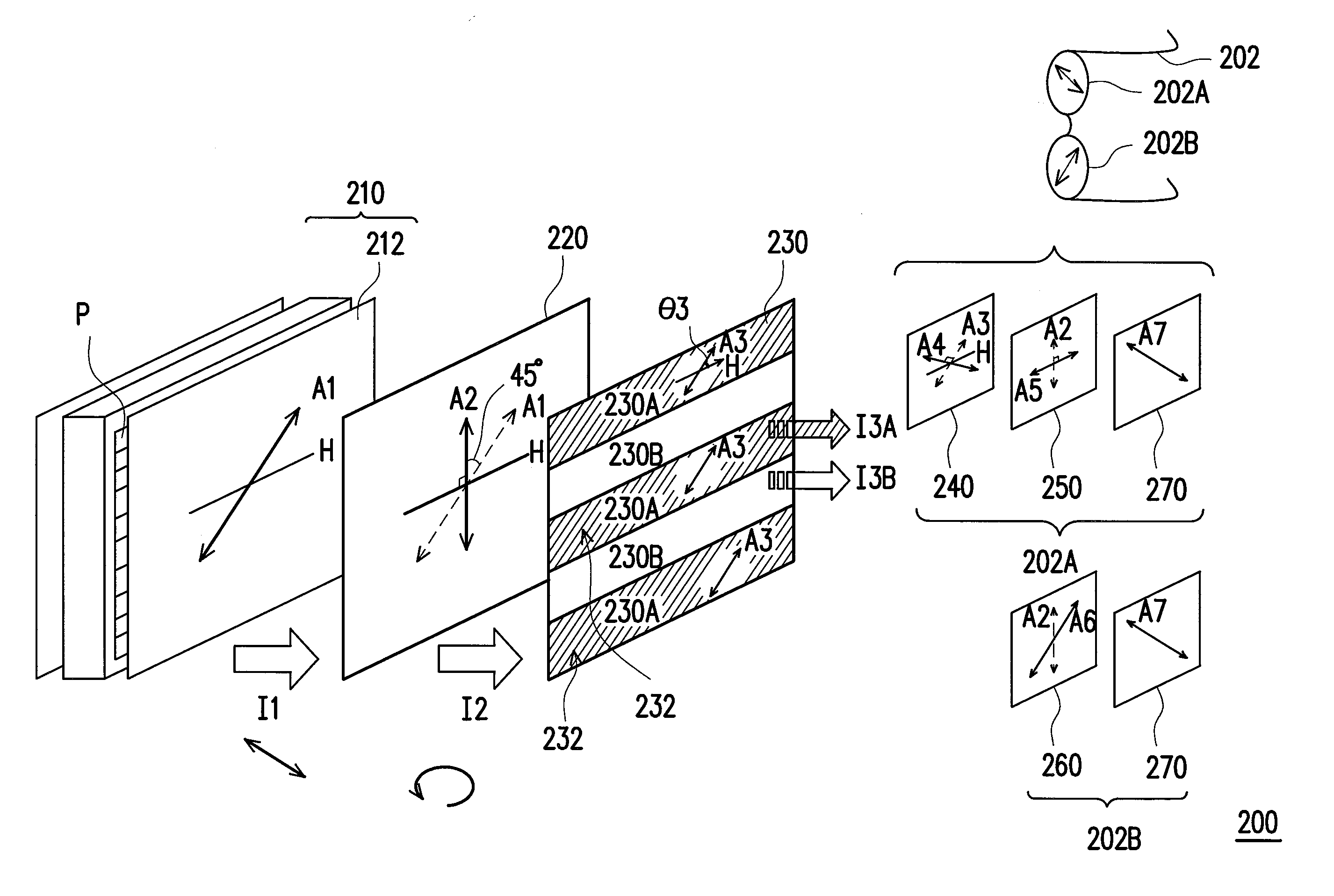
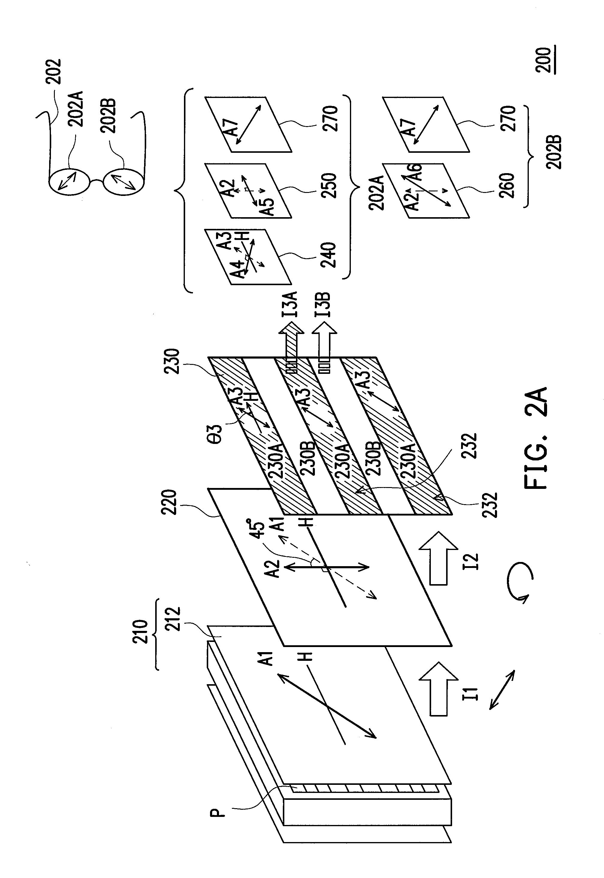
[0017]FIG. 2A illustrates a three-dimensional display apparatus according to a first embodiment of the present disclosure. Referring to FIG. 2A, the three-dimensional display apparatus 200 is adapted to be observed by an observer wearing a pair of polarized glasses 202. The pair of polarized glasses 202 has a first circularly polarized eyeglass 202A and a second circularly polarized eyeglass 202B that have different polarization directions. The structures of the first circularly polarized eyeglass 202A and the second circularly polarized eyeglass 202B are shown in FIG. 2A. The first circularly polarized eyeglass 202A may be considered as a combination of a first quarter-wave plate 250, a half-wave plate 240, and a linear polarizer 270. The second circularly polarized eyeglass 202B may be considered as a combination of a second quarter-wave plate 260 and a linear polarizer 270. In addition, the three-dimensional display apparatus 200 further includes a display panel 210, a third quar...

Example

Second Embodiment

[0033]FIG. 5 illustrates a three-dimensional display apparatus according to a second embodiment of the present disclosure. Referring to FIG. 5, the three-dimensional display apparatus 300 is similar to the three-dimensional display apparatus 200 of the first embodiment except that the polarization direction of the linearly polarized image outputted by the display panel 210 of the three-dimensional display apparatus 300 is substantially perpendicular to the horizontal direction H of the three-dimensional display apparatus 300. It should be noted that the included angle θ2 formed between the optical axis A2 of the third quarter-wave plate 320 and the horizontal direction H may be 45 degrees or 135 degrees, and in the present embodiment is, for example, 45 degrees. The included angle θ3 formed between the optical axis A3 of the λ / 2 phase-retardation region 230A of the half-wave plate and the horizontal direction H is, for example, any included angle between 45 degrees ...


PUM


Abstract

A three-dimensional display apparatus including a pair of polarized glasses having first and second circularly polarized eyeglass with different polarization directions, a display panel displaying a linearly polarized image, a third quarter-wave plate and a patterned half-wave plate is provided. The first circularly polarized eyeglass has a first quarter-wave plate and a first half-wave plate. The second circularly polarized eyeglass has a second quarter-wave plate. The angle between polarization direction of the linearly polarized image and optical axis of the third quarter-wave plate is 45 degrees. The angle between optical axis of the first quarter-wave plate and optical axis of the third quarter-wave plate is 90 degrees. The angle between optical axis of the first half-wave plate and optical axis of the patterned half-wave plate is 90 degrees. The angle between optical axis of the second quarter-wave plate and optical axis of the third quarter-wave plate is 55-125 degrees.

Description

CROSS-REFERENCE TO RELATED APPLICATION[0001]This application claims the priority benefit of Taiwan application serial no. 98108622, filed on Mar. 17, 2009. The entirety of the above-mentioned patent application is hereby incorporated by reference herein and made a part of specification.BACKGROUND OF THE DISCLOSURE[0002]1. Technical Field[0003]The present disclosure relates to a three-dimensional display apparatus.[0004]2. Description of Related Art[0005]With development of technology, people are pursuing higher and higher quality in their material and sprit lives. For example, at the era in which the technology improvement is never ending, people wish to fulfill their creative imagination by using a display apparatus to have a simulated feeling as if it was really happening. Therefore, enabling the display apparatus to display three-dimensional pictures or images has become one of the most important goals to achieve in the current display technology.[0006]In terms of the method of u...

Claims


Application Information

Patent Timeline
IPC IPC(8): G02B27/26G02B30/25
CPCG02B27/26G02B30/25
Inventor HSU, WEI-LIANGTSAI, CHAO-HSUCHENG, SHU-CHUAN
Owner IND TECH RES INST
Why Eureka
Try Eureka