Pedicle screw including stationary and movable members for facilitating the surgical correction of spinal deformities

a technology of pedicle screw and movable member, which is applied in the field of orthopedic surgery, can solve problems such as difficulty in properly aligning the plurality of pedicle screw for subsequent insertion

Inactive Publication Date: 2010-09-23
UNIVERSITY OF TOLEDO
View PDF10 Cites 32 Cited by
  • Summary
  • Abstract
  • Description
  • Claims
  • Application Information

AI Technical Summary

Benefits of technology

[0007]This invention relates to a pedicle screw for use in the treatment of a spinal deformity. The pedicle screw includes a head assembly and a fastener portion that extends from the head assembly. The fastener portion extends from the head assembly and is adapted to be secured to a vertebra of a spinal column. The head assembly includes a stationary member and a movable member. The movable member is supported on the stationary member for movement (such as pivoting m...

Problems solved by technology

Although known pedicle screws have functioned satisfactorily, it has been found that in some instances, it can be difficult to properly align the plurality of pedicle screws for subsequent insertion and retention of the longitudi...

Method used


Image

  • Pedicle screw including stationary and movable members for facilitating the surgical correction of spinal deformities
  • Pedicle screw including stationary and movable members for facilitating the surgical correction of spinal deformities
  • Pedicle screw including stationary and movable members for facilitating the surgical correction of spinal deformities

Examples


first embodiment

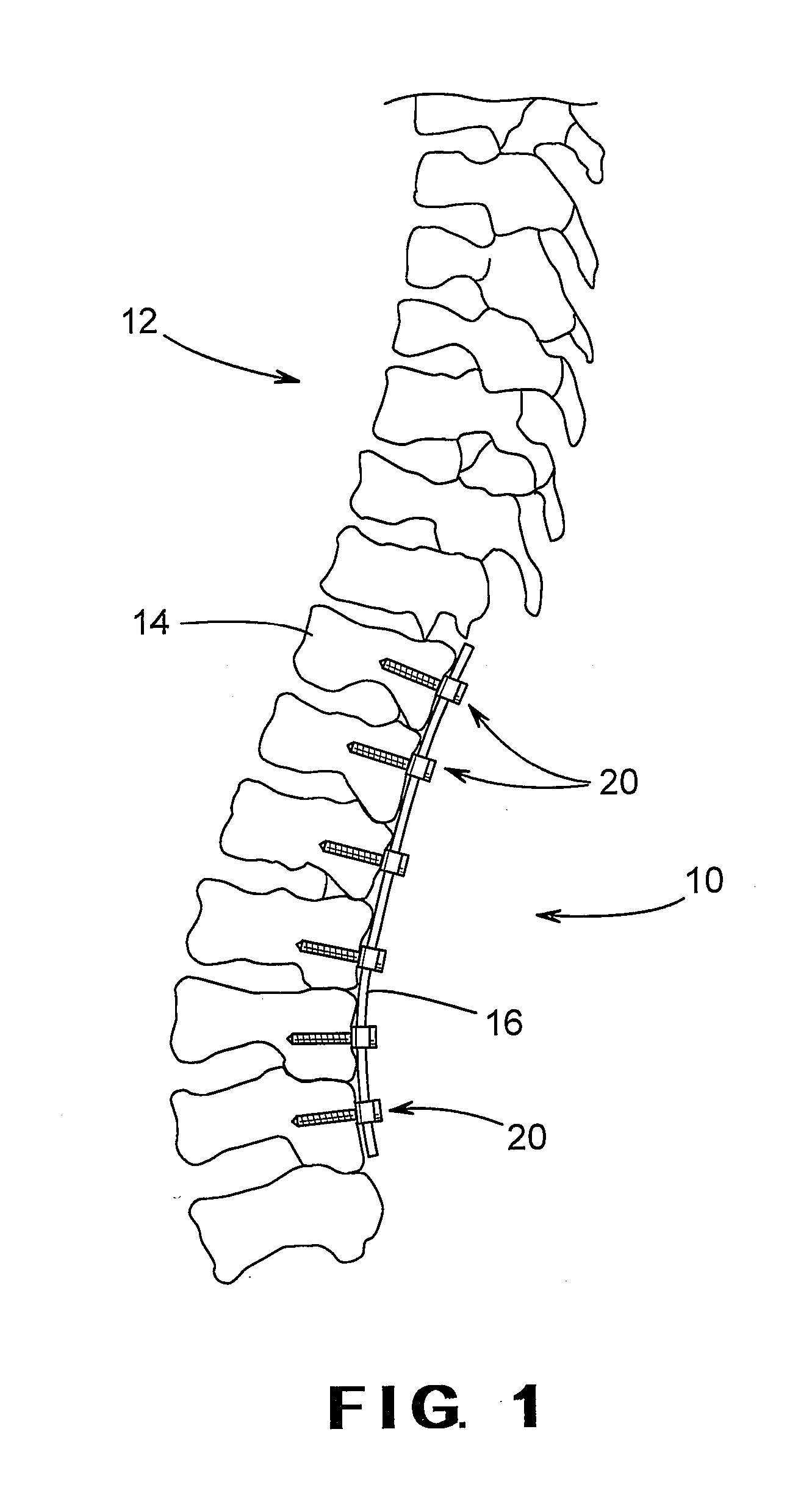
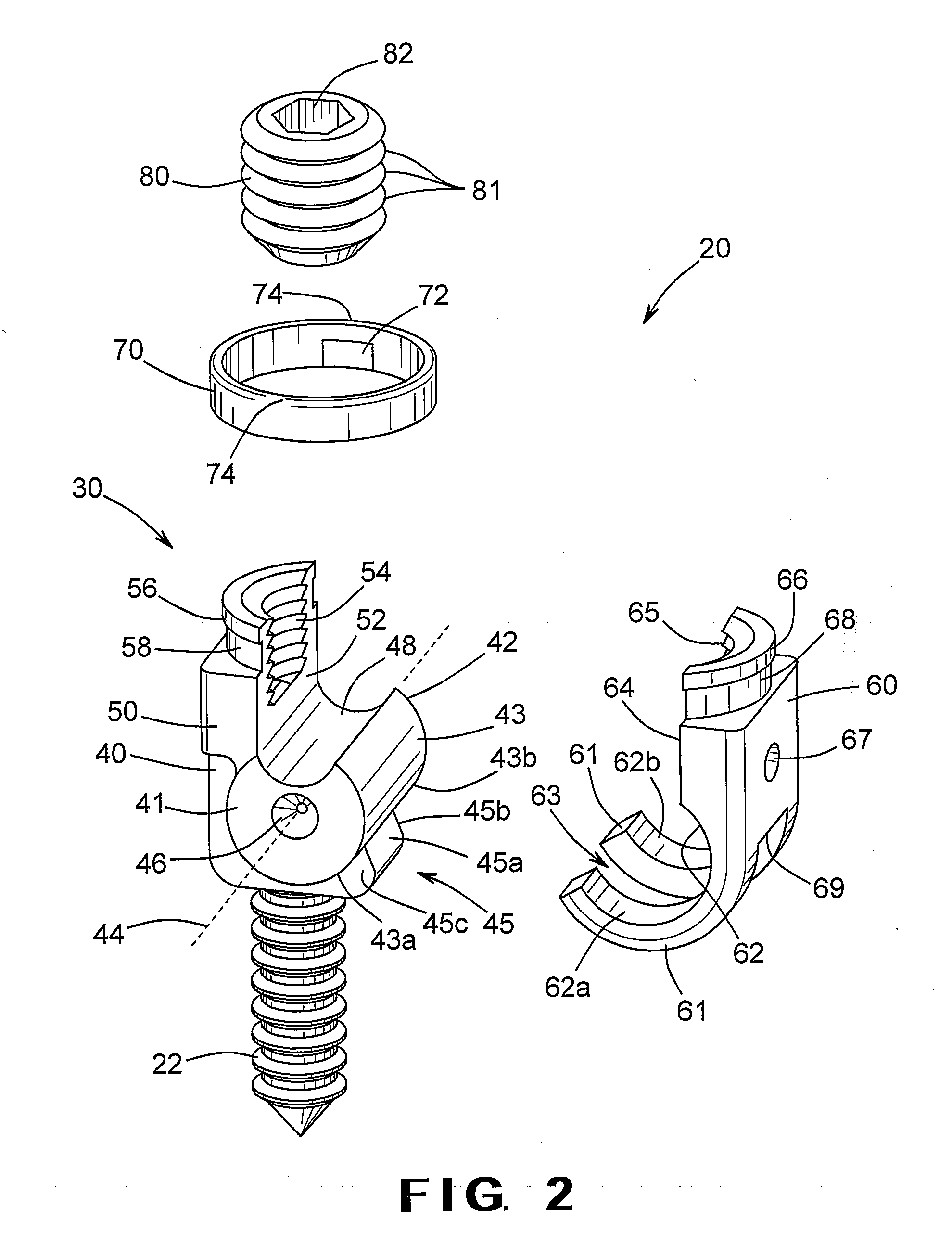
[0030]Referring now to FIG. 2, there is illustrated an exploded assembly view of one of the pedicle screws 20. As shown therein, the pedicle screw 20 includes a head assembly, indicated generally at 30, having a fastener portion 22 extending therefrom. The head assembly 30 may include a stationary member 40, a movable or pivot member 60, a locking member 70, and a retention member 80. As will be explained in detail below, the stationary member 40 and the pivot member 60 of the head assembly 30 cooperate to define a generally U-shaped yoke for receiving and securing the alignment rod 16 to the pedicle screw 20. The head assembly 30 may thus facilitate proper alignment of the spinal column 12 and assist in installation of the spinal fixation device 10.

[0031]The head assembly 30 is formed integrally with or connected to the fastener portion 22 for mounting or otherwise securing the head assembly 30 to one of the vertebrae 14. In the illustrated embodiment, the fastener portion 22 is an...

second embodiment

[0068]FIG. 7 is a side elevational view of a modified pivot member 60A that can be used in a pedicle screw in accordance with this invention. The modified pivot member 60A has an increased lower anterior body thickness with a radii blend relative to the above-described pivot member 60, which is shown by a dotted line. The modified pivot member 60A is otherwise identical in structure and operation to the above-described pivot member 60.

third embodiment

[0069]FIG. 8 is a side elevational view of another modified pivot member 60B that can be used in a pedicle screw in accordance with this invention. The modified pivot member 60B has an increased lower anterior body thickness with right angled flat surfaces on the mounting members 61 adjacent to the pivot engagement surface 62, as compared with the above-described pivot member 60 (which is shown by a dotted line). The modified pivot member 60B is otherwise identical in structure and operation to the above-described pivot member 60.


PUM


Abstract

A pedicle screw for use in the treatment of a spinal deformity includes a head assembly and a fastener portion extending from the head assembly. The pedicle screw includes a head assembly and a fastener portion that extends from the head assembly. The fastener portion extends from the head assembly and is adapted to be secured to a vertebra of a spinal column. The head assembly includes a stationary member and a movable member. The movable member is supported on the stationary member for movement (such as pivoting movement) relative thereto between an opened position and a closed position. When the movable member is in the opened position, the head assembly is adapted to receive a longitudinal member therein for treatment of a spinal deformity. Thereafter, the movable member can be moved to the closed position to properly align the pedicle screw with the longitudinal member. A locking member and a retention member can then be used to maintain the movable member in the closed position.

Description

STATEMENTS REGARDING FEDERALLY SPONSORED RESEARCH OR DEVELOPMENT AND CROSS REFERENCE TO RELATED APPLICATIONS[0001]This invention was not made with any government support. This application claims the benefit of U.S. Provisional Application No. 61 / 162,631 filed Mar. 23, 2009, the disclosure of which is incorporated herein by reference.BACKGROUND OF THE INVENTION[0002]This invention relates in general to the field of orthopedic surgery and more specifically to the area of spinal surgery. In particular, this invention relates to an improved structure for a pedicle screw that is adapted to facilitate the installation of a spinal fixation device that can assist in the proper alignment of vertebrae in a spinal column.[0003]Scoliosis is a medical condition in which a spinal column is abnormally curved from side to side. The abnormal curvature is often three dimensional in nature, including both a lateral component and a rotational component. In many patients having severe scoliosis, surgica...

Claims


Application Information

Patent Timeline
IPC IPC(8): A61B17/88A61B17/86
CPCA61B17/7032A61B17/7037A61B17/7035
Inventor BIYANI, ASHOKDURIVAGE, GARY
Owner UNIVERSITY OF TOLEDO
Why Eureka
Try Eureka