Method of Semi-Automatic Ballast Replacement

Active Publication Date: 2010-09-23
LUTRON TECH CO LLC
View PDF20 Cites 55 Cited by
  • Summary
  • Abstract
  • Description
  • Claims
  • Application Information

AI Technical Summary

Benefits of technology

[0012]According to an embodiment of the present invention, a semi-automatic procedure of replacing a first device with a second device in a lighting control system requires limited user input to facilitate the replacement procedure. The method comprises the steps of: (1) a controller identifying an operational configuration of the first device; (2) determining tha

Problems solved by technology

This method can be very time-consuming for a user.
This prior art method of reconfiguration can be tedious as the user must input the serial numbers of both the replace

Method used


Image

  • Method of Semi-Automatic Ballast Replacement
  • Method of Semi-Automatic Ballast Replacement
  • Method of Semi-Automatic Ballast Replacement

Examples


Embodiment Construction

[0024]The foregoing summary, as well as the following detailed description of the preferred embodiments, is better understood when read in conjunction with the appended drawings. For the purposes of illustrating the invention, there is shown in the drawings an embodiment that is presently preferred, in which like numerals represent similar parts throughout the several views of the drawings, it being understood, however, that the invention is not limited to the specific methods and instrumentalities disclosed.

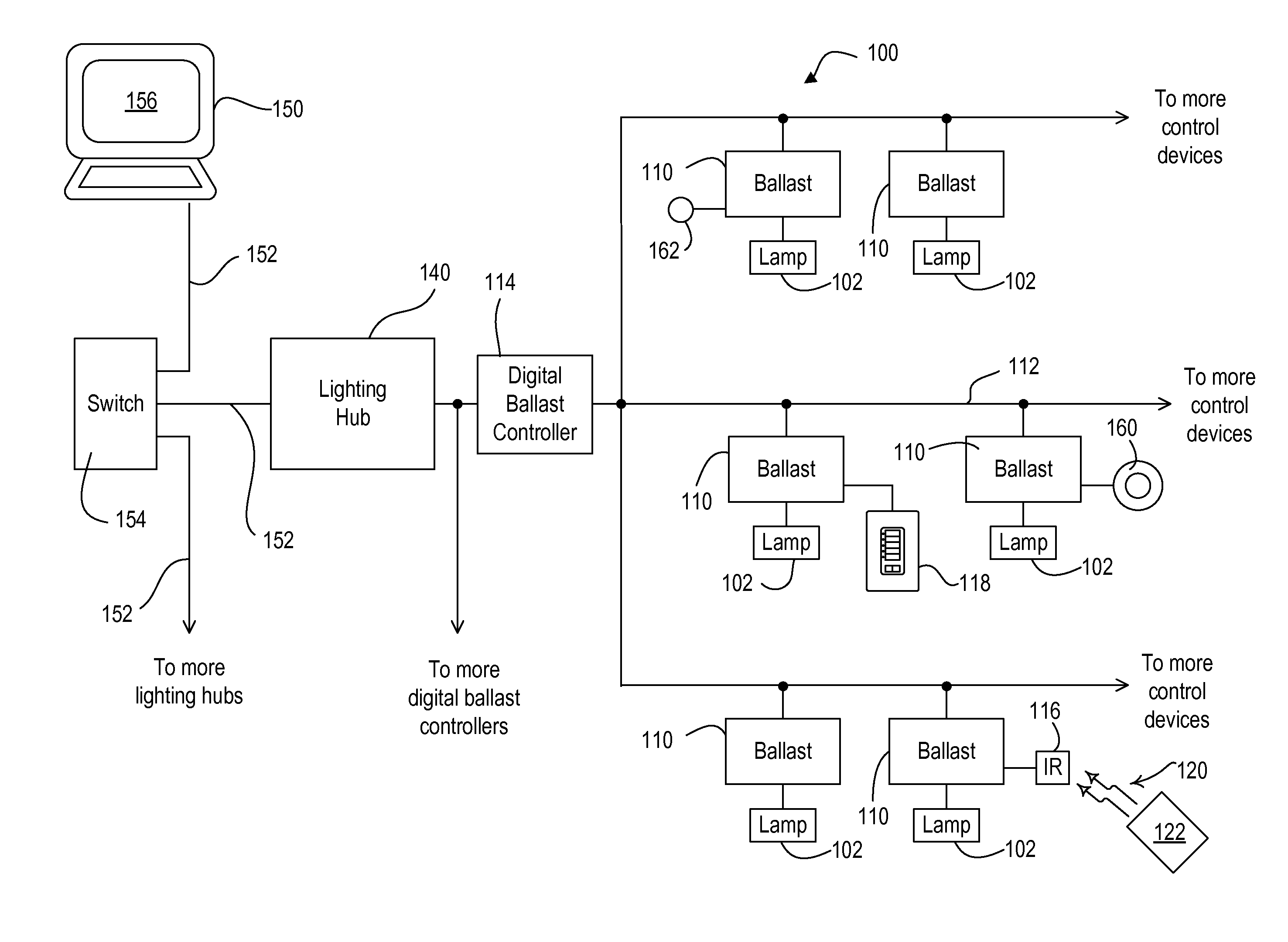
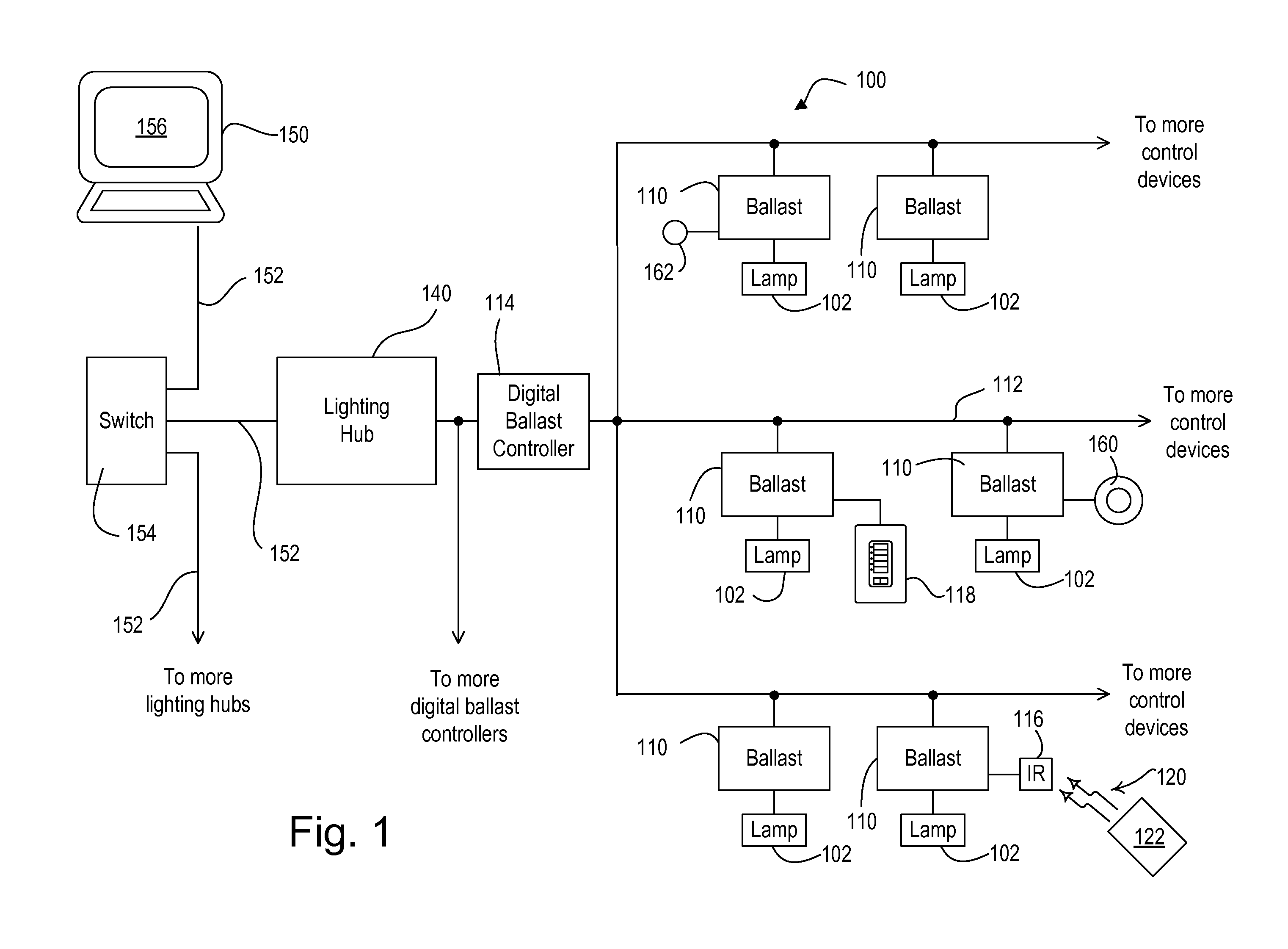
[0025]FIG. 1 is a simplified block diagram of a lighting control system 100 according to the present invention. The lighting control system 100 is operable to control the level of illumination in a space by controlling the intensity level of the artificial lighting in the space. As shown in FIG. 1, the lighting control system 100 is operable to control the amount of power delivered to (and thus the intensity of) a plurality of lighting loads, e.g., a plurality of fluorescent lam...


PUM


Abstract

The present invention relates to a semi-automatic method of replacing a ballast within a lighting control system, such that the new replacement ballast can operate in the same manner as the ballast that was replaced. If multiple ballasts in a lighting control system are removed from the system and multiple new ballasts are installed to replace those ballasts, any operational configurations such as group configurations or area information associated with each removed (missing) ballast must be assigned to the proper new replacement ballast. The semi-automatic replacement method relies upon the operational configurations of the removed ballast to help a user identify which new ballast should replace each missing ballast.

Description

RELATED APPLICATIONS[0001]This application claims priority from commonly-assigned U.S. Provisional Application Ser. No. 61 / 162,153, filed Mar. 20, 2009, entitled METHOD OF SEMI-AUTOMATIC BALLAST REPLACEMENT, the entire disclosure of which is hereby incorporated by reference.BACKGROUND OF THE INVENTION[0002]1. Field of the Invention[0003]The present invention relates to a semi-automatic method of replacing a device within a load control system, such that the new replacement device can operate in the same manner as the device that was replaced. Particularly, the invention relates to a method of configuring replacement ballasts in a lighting control system, and the method requires limited user input.[0004]2. Description of the Related Art[0005]A typical prior art load control system is operable to control the amount of power delivered to one or more electrical loads, such as lighting loads or motor loads, from an alternating-current (AC) power source. A lighting control system generall...

Claims


Application Information

Patent Timeline
IPC IPC(8): G05B9/03G06F17/00
CPCH05B37/02H05B37/0272H05B37/0245H05B47/10H05B47/175H05B47/19H05B47/195
Inventor BENETZ, FRANK H.BULL, JOHN H.HINDS, THOMAS RICHARDHOWE, WILLIAM H.
Owner LUTRON TECH CO LLC
Why Eureka
Try Eureka