Shape defect factor identification method, device, and program

Active Publication Date: 2010-09-23
TOYOTA JIDOSHA KK +1
View PDF1 Cites 9 Cited by
  • Summary
  • Abstract
  • Description
  • Claims
  • Application Information

AI Technical Summary

Benefits of technology

[0008]The present invention aims to provide a technique capable of rapidly, reliably, and easily identifying the factor for shape defect of wo

Problems solved by technology

Numerous automobile parts have a complex shape such as curving shape or cross-sectional shape changing at any portion, and thus identification of the cause of elastic recovery of deformation is difficult and it takes time to investigate the cause.
The cause of elastic recovery of deformation differs depending on the shape and the material of the work, and thus it was difficult to perform appropriate countermeasures on the elastic recovery of deformation for every work in a short period of time after clarifying the caus

Method used


Image

  • Shape defect factor identification method, device, and program
  • Shape defect factor identification method, device, and program
  • Shape defect factor identification method, device, and program

Examples


Embodiment Construction

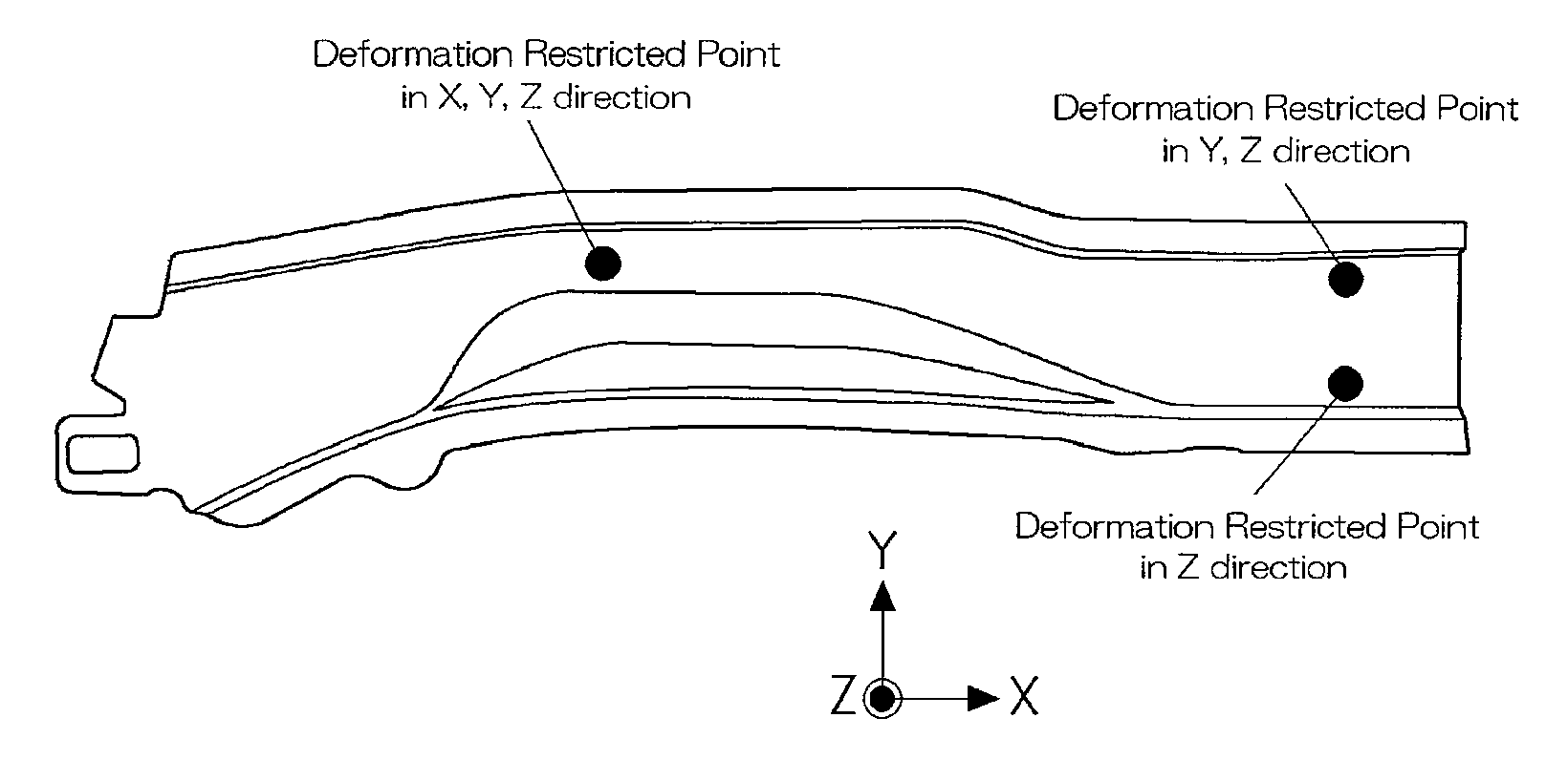
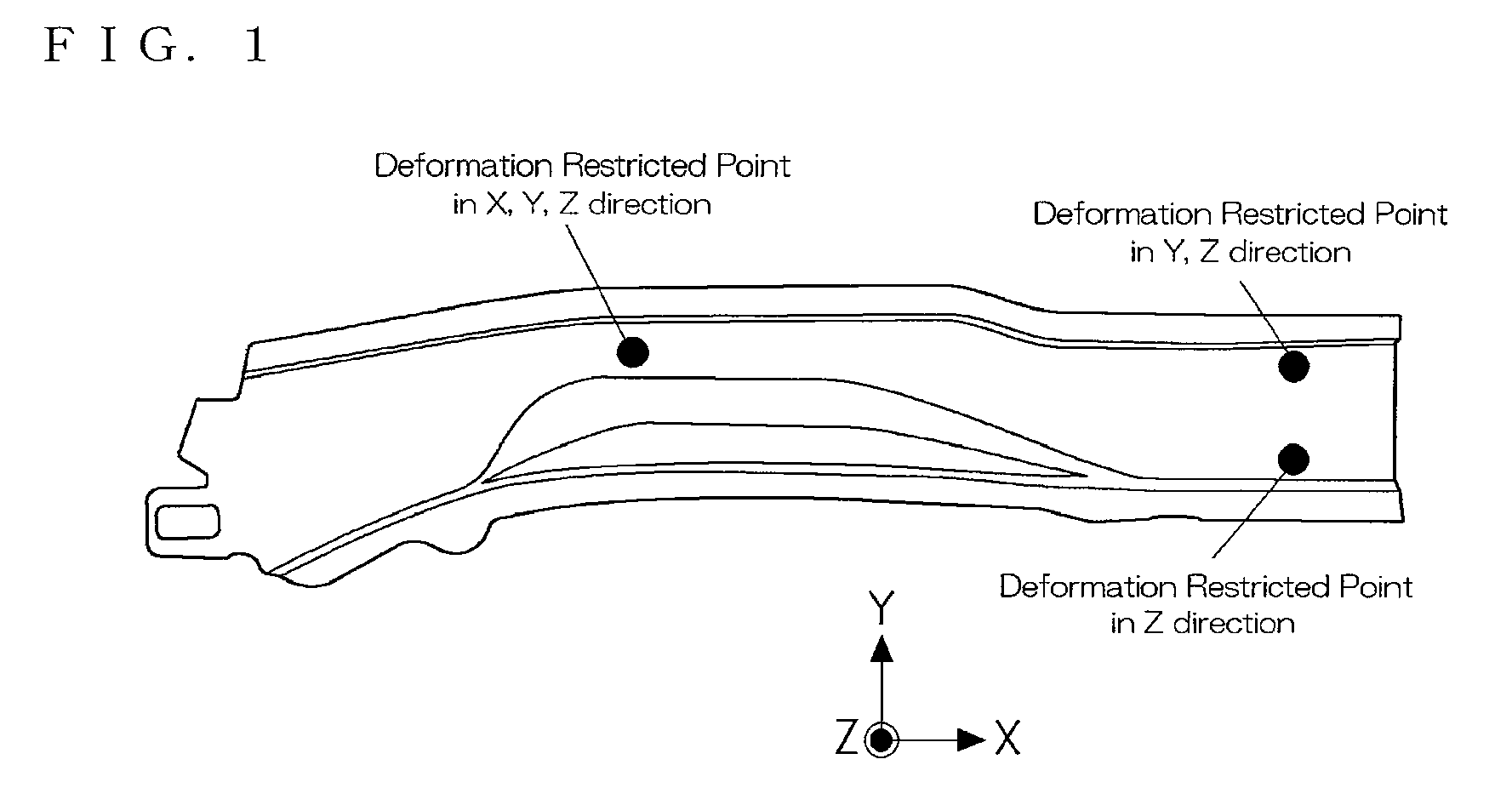
[0034]FIG. 1 is a view showing work according to an embodiment of the present invention. FIG. 2 is a view showing a displacement amount after elastic recovery of the work. FIG. 3 is a cross-sectional view taken along F-F line of FIG. 2.

[0035]FIG. 4 is a view showing a configuration of a shape defect factor identification device. FIG. 5 is a flowchart of a process for identifying the main influence region. FIG. 6 is a flowchart of a process for identifying the main influence stress component. FIG. 7 is a flowchart of a process for determining the influence of distribution in a plate-thickness direction of stress. FIG. 8 is a flowchart of a process of a shape defect factor identification program.

[0036]FIG. 9 is a view showing an embodiment of division of the work into regions in a long side direction. FIG. 10 is a view describing an idea of dividing the work into regions in a short side direction. FIG. 11 is a view showing an embodiment of dividing the work into regions in the short s...


PUM

PropertyMeasurementUnit
Thicknessaaaaaaaaaa
Dimensionaaaaaaaaaa
Stress optical coefficientaaaaaaaaaa

Abstract

Provided is a method for rapidly, surely, and easily identifying a factor of a shape defect of an artifact attributed to elastic recovery of deformation upon molding by using the numeric value simulation technique, thereby eliminating lowering of dimension accuracy. The method includes a step of calculating a stress distribution and distortion distribution working on an artifact before elastic recovery; a step of calculating a deformation amount δ0 based on the elastic recovery of an evaluation point when the stress distribution is given to the artifact shape before the elastic recovery; a step of dividing the artifact shape into a plurality of regions and calculating a deformation amount δn based on the elastic recovery of the evaluation point when the stress distribution is given to each of the regions of the artifact shape before the elastic recovery; and a step of comparing the deformation amount δ0 and the deformation amount δn and identifying a region where the difference between them is minimum as a main affect region, i.e., a stress distribution region which most affects the shape defect of the evaluation point before and after the elastic recovery.

Description

TECHNICAL FIELD[0001]The present invention relates to a technique of identifying the factor of dimensional accuracy defect (shape defect) of work arising from elastic recovery of deformation in plastic forming such as casting, rolling, extrusion processing, drawing process, press working, or the like.BACKGROUND ART[0002]It is conventionally known that when performing plastic forming, a dimensional accuracy of the work lowers due to the elastic recovery (spring back) that appears when restriction by a molding tool, such as the die which applies deformation on the material to be processed, is released from the work.[0003]Numerous automobile parts have a complex shape such as curving shape or cross-sectional shape changing at any portion, and thus identification of the cause of elastic recovery of deformation is difficult and it takes time to investigate the cause. The cause of elastic recovery of deformation differs depending on the shape and the material of the work, and thus it was ...

Claims


Application Information

Patent Timeline
IPC IPC(8): G06F19/00G01L1/00B21D22/00G06F17/50
CPCG06F17/5018Y02T10/82G06F2217/41G06F2217/16G06F30/23G06F2111/10G06F2113/22B21C51/00B21D7/03B21D7/12
Inventor NONOMURA, KIYOSHIIWAYA, JIROYAMANO, TAKAYUKI
Owner TOYOTA JIDOSHA KK
Why Eureka
Try Eureka